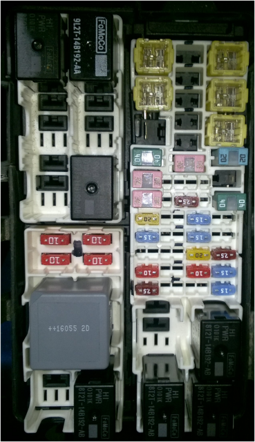
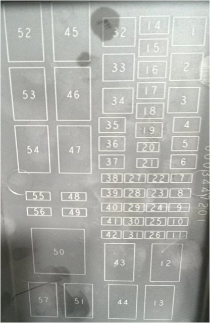
Wow okay. Yeah those are "critical" systems. As I understood it, that's powering the DRLs directly and not a relay coil. If it is powering only a relay coil, then change that 5A to a fast-acting 1A. If it is powering the DRLs direclty, I'd certainly change how that's done. First, it's best to choose a related and non-critical circuit. Second, I had tested an Add-A-Circuit (AAC) product. The way they *should* be designed, is to have the secondary fuse, slave off of the original. If it were designed that way, you would only have the maximum potential of 15A going over the OEM wire that is feeding that fuse. But unfortunately that's not how these are designed. Instead you have the potential of 15A and another 5A, going over that OEM wire harness. That's a potential 33% increase in load. Take out your AAC and probe it out with a circuit tester. You'll be able to confirm what I've been saying. It's just something that we all assumed was designed right, but unfortunately wasn't and isn't. I know of no AAC type products that claim to do it right. But that's not to say that they don't exist.
It's certainly true that nothing may ever become of it. But what if it does? The potential consequences are too much to risk. Camshaft sensor consumption should be consistent. But it's a bright frigid morning and the O² sensors are running near peak loads heating themselves; DRLs on high. Wire gets a little warm, but nothing ever becomes of it. But fast forward many Winters down the road. That wire that spent some periods running too warm, has now melted through its insulation, and is now working on adjacent wires. Different oxygen sensors can even operate on higher tolerances; placing the circuit even closer toward the 15A maximum. The potential consequences are too much to risk.
.
Earlier this year I purchased a new motorcycle battery that sat on the store shelf too long and was allowed to run down to ~10.3v. I recharged it to 12.6 overnight and installed it in the motorcycle. Wouldn't crank at all... just the characteristic rapid clicking from the starter motor. So I grabbed my original battery (still good) to use as a jump start-assist. I connected it using the 18 or 20 gauge alligator clip wires laying around. I was just curious whether it would work. (I like to experiment sometimes and didn't care if I burned them up.) Not only did it work, it seemed work well enough. Several extended cranks and starts. (trying to pin down a running issue) Warm to the touch, but the wires believe it or not, looked good. Then I pulled them out a few weeks later and noticed this... https://1drv.ms/u/s!AhsZJDCN8kMMgaRaapkIsVm2Wuf-2A This is what starts to occur gradually, slowly, potentially over years, inside a wire harness that experiences brief periods of overload. The wires should've been fourteen or better gauge, instead of the eighteen or twenty I experimented with.


