Right, so this was a rollercoaster. As it turns out, the leveling motors were not my issue, shipping damage was. Both my sideways adjustment and my static pivot balls had popped out of their sockets. The sideways adjuster was easy enough to get back on, but the static pivot was a giant PITA. I got it all back together though! So all is well, and my lights work, and are able to be aimed. Here are some pictures of that progress.
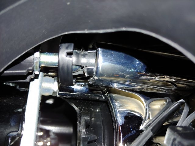
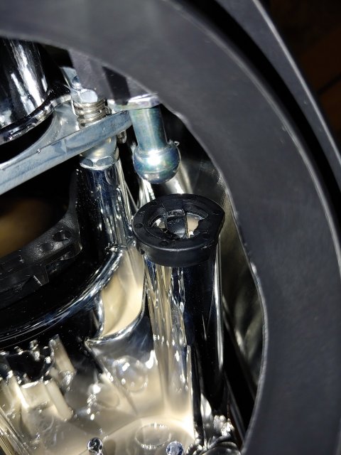
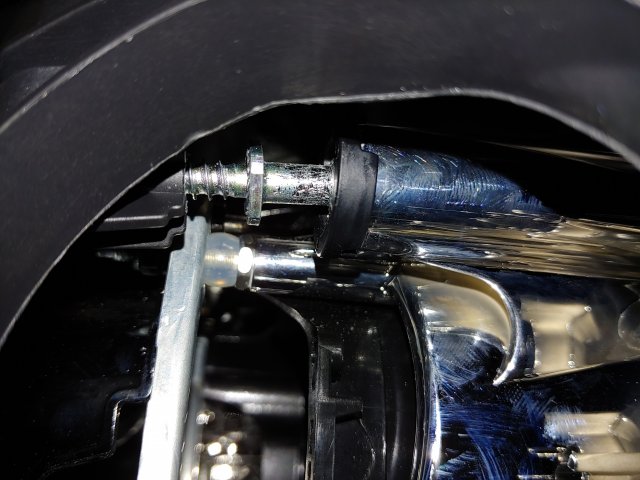
Enough about that though, the real progress for the community tonight was that I was able to figure out how to control the leveling motors, and it is fantastically simple.
Lets start with the headlight connector pinout, since none of the ones I have seen posted for the euro lights are 100% accurate. I traced every wire from the connector, and followed them to termination, so I am confident this is correct, at least for OEM.
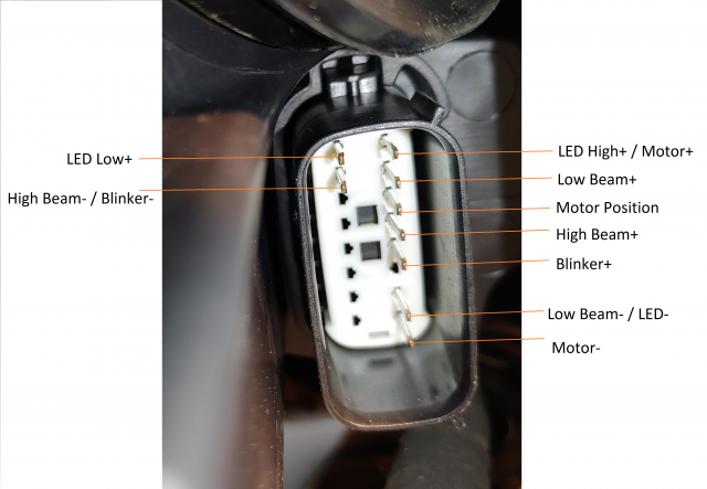
As we can see, we have 3 wires listed for motor function, this makes sense, as if we look at the motor in the housing we can see a small 3 pin connector.
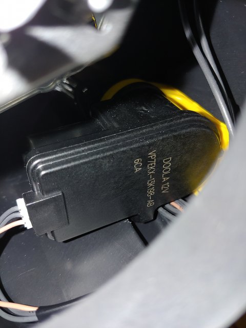
I first took chalitunas advice, and connected 12V from LED High+/Motor+ to Motor-, and sure enough, the motor retracted. Now I had to get it to extend. Well first I tried every combination of 12V between the three motor wires, and got absolutely nowhere.
At this point I almost gave up, because I hadnt found the popped out ball joints yet, and assumed I made it even worse by retracting the motor. I was about to accept the fact that I had ruined a $400 headlight. In a last ditch effort, I decided to Google the part number on the back of that leveling motor, not expecting to find much.
I hit gold. Most of what showed up was just scrap yards selling them, but one result caught my eye. It was a Russian video that appeared to be a teardown of one of the motors.
https://youtu.be/DdmV605yxZ
4
I have no idea what most of that video is about, but for about 10 seconds at the end they show a close up of the PCB inside, and a few seconds of that are even in focus, which was all I needed to see. I grabbed this screenshot of the board.
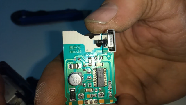
It's hard to see, but that chip says TDA3629T. Googling that I found this datasheet.
http://citeseerx.ist.psu.edu/viewdoc/download?doi=10.1.1.434.3172&rep=rep1&type=pd
f
Well look at that, its a purpose built headlight level controller (albeit an old one). Reverse engineering the circuit as best I can from the board screenshot I get this.
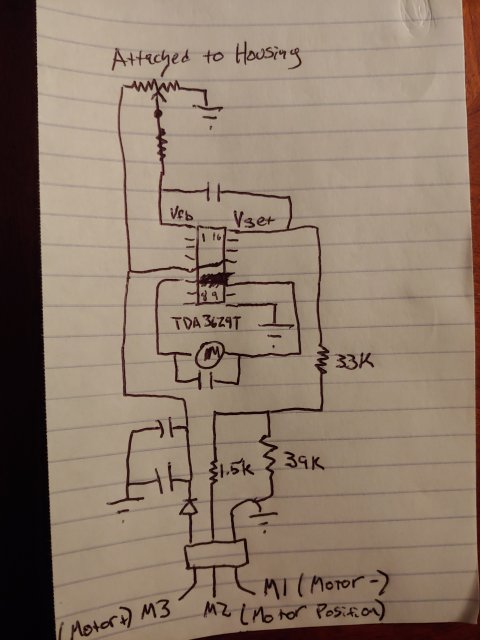
So, between the schematic and the datasheet, I was able to figure out that basically it is just looking for an analog voltage that is between about 1V and just below battery voltage on the Motor Position pin. The easiest way to get that is a potentiometer between all 3 of the pins, with the two ends hooked to Motor+ and Motor-, and the adjustable wiper hooked to Motor Position. Then connect Motor- to ground, and it will operate anytime the LEDs are in high mode. Like this.
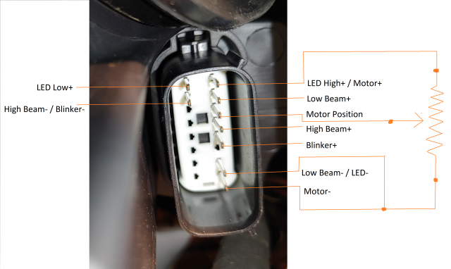
To get the full range of the motor extra resistors may be needed, and I havent figured out the ideal potentiometer value yet, but hey, I did all this on my phone in the garage.
I had a 10K ohm potentiometer in the parts box, I hooked it up with alligator clips and my M12 drill battery and I was able to move the motor with the knob.
If we want discreet positions like OEM all we need is a multi-position knob switch and a resistor divider with multiple taps. Could even use 3 resistors and a toggle switch for a simple 2 position low and high.
If there is enough interest I can figure out the exact values of resistors to get the max extension, but this should be easy to add in if you really want it, just 3 wires into the cabin, and 2 extra pins into the headlight harness.
This could also be done with a microcontroller using an analog output and an op-amp, if we wanted to make it programmable.
Keep in mind the one restriction with this is that they only work with the LED on high mode. So if you have VirtualRonins factory style harness setup, or the 1 wire always high mod, you will be fine. If you run low LED with the headlight on, the adjusters would not work.
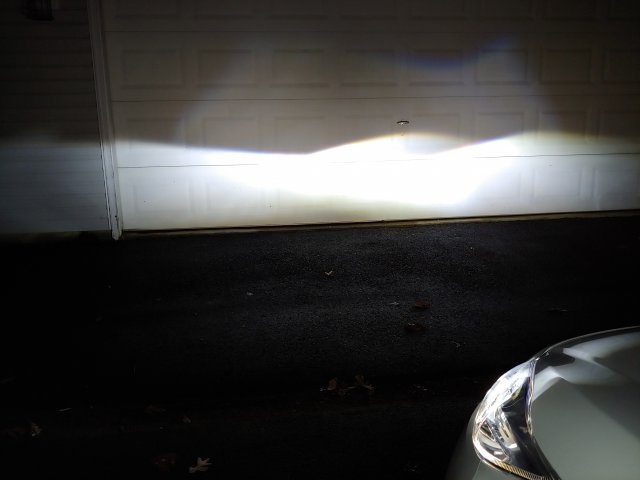
Here is my end result with aukee LEDs, still need to find a flatter spot to aim them, but good enough for now. The dust boots still fit with these LEDs, how long they will last sealed up is another question.


