-
Sign Up! To view all forums and unlock additional cool features
Welcome to the #1 Fiesta ST Forum and Fiesta ST community dedicated to Fiesta ST owners and enthusiasts. Register for an account, it's free and it's easy, so don't hesitate to join the Fiesta ST Forum today!
WestcoaST Performance blue build
- Thread starter westcoaST
- Start date
Thread Starter
#102
Wilwood BBK
I used the 3 day weekend to install my Willwood big brake kit with polymatrix pads. I got this kit several months ago, but had some problems getting the right Motive brake bleeder kit for the Fiesta ST. The correct numbers are 1108 or 1118 for the kit or just the adapter. The instructions that come with the Wilwood kit are good, but the photos are really small. There are very few bolts that need to be removed from the OEM brakes to allow for the installation of the BBK.
This is what the brake kit consists of:
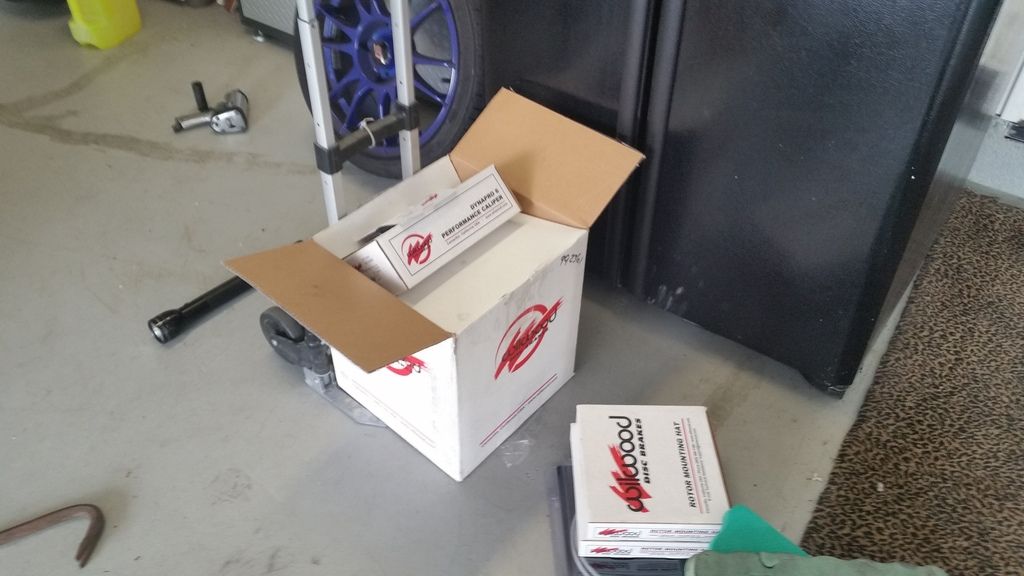
Two rotors
Two rotor hub
Two calipers, one LH and the other RH
Two rotor "shims" that go underneath the rotor on the hub
Two hub to caliper brackets
Assorted fasteners to mate the rotor to the rotor hub. These are star fasteners, so you will need a good T40 wrench. I used a 3/8" drive for my torque wrench, and various sockets for attaching the brackets, the calipers. I used a 1/2" torque wrench for these larger bolts. Wilwood provides the torque requirements for these fasteners.
Important, you will need a 1/4" and 5/32" combination wrench to bleed the front and rear brakes. I also purchased a gemini brake bleeder bottle, but you could use an empty soda bottle. I also had a 1 liter can of Dot 4 ATE blue brake fluid. You will need a tygon tube to assist in bleeding the brakes.
Taking the OEM brakes off is really easy, especially since you won't need to put them back on. I removed the bolt for the slider pin, and this allowed me to rotate the caliper out of the way. The pads either stay in place or come along for the ride.
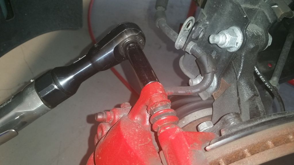
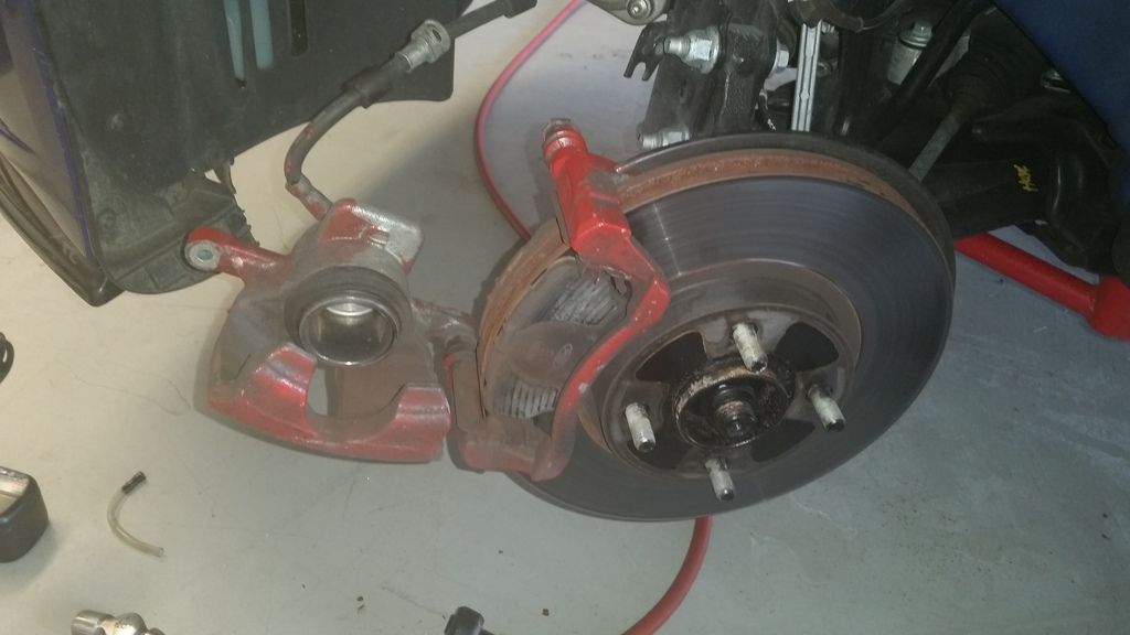
There are two bolts on the backside of the hub which connect the caliper to the hub. Remove these and the caliper bracket comes right off.
There is a 10mm bolt holding on the brake line to the strut. Remove this bolt and set it aside. I placed the caliper on a box to relieve the strain on the brake line.
Now, this is important, get a piece of hose that will fit over the hard brake line BEFORE you unscrew the hard brake line from the soft brake line. I used a piece of tygon tubing with a rubber plug on the end of it. You do not want to lose too much brake fluid, especially since as fluid goes out, air can get in.
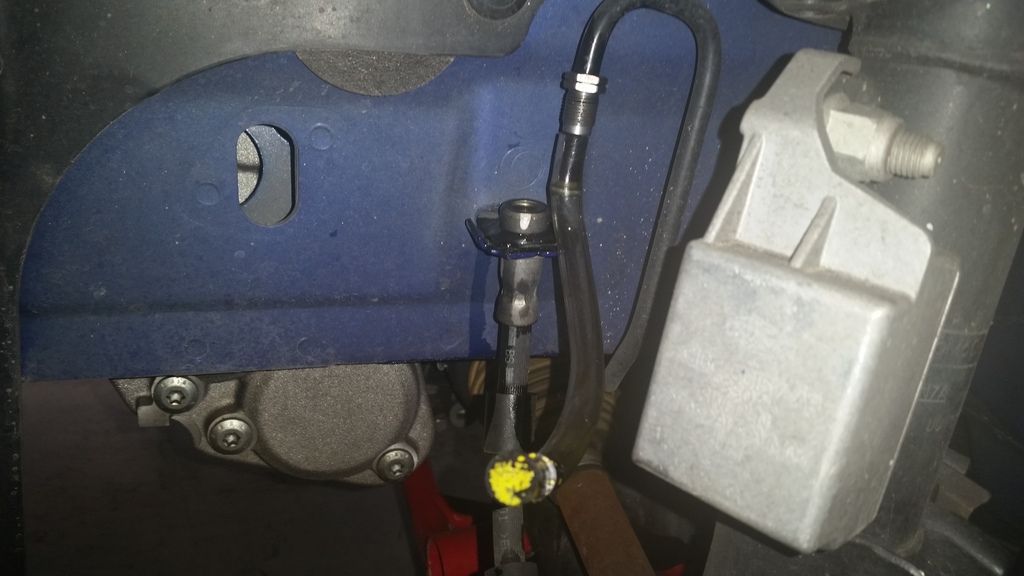
There is a forked brake clamp that holds the OEM brake line to the frame. It has a hole at the end. I used a screwdriver and pair of pliers to remove it. The OEM caliper is now removed. I put it and its brother aside, inside of a plastic tray to allow the brake fluid to come out. Do not get brake fluid on your paint. If you do, rinse it with clear water. I used Isopropyl alchol, as it will cut the fluid faster when it get on the floor.
Getting your rotors off requires a dead blow plastic hammer, with lots of rotation.
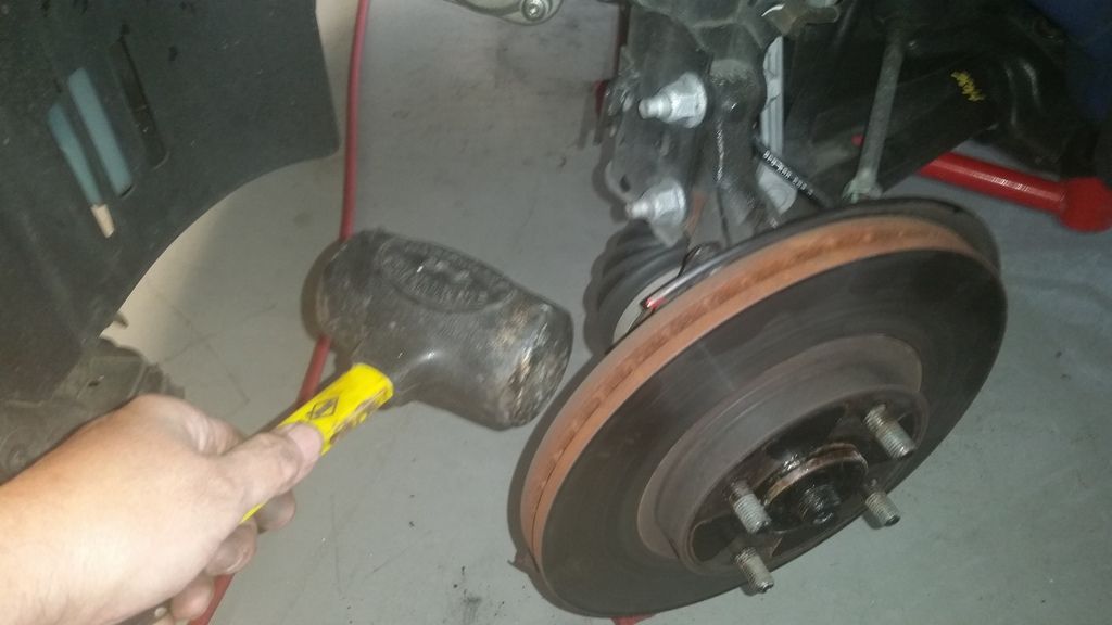
You need to assemble your rotors. The hard part is torquing the star fasteners to connect the hat to the rotor. I placed masking tape on the rotor hat (to protect it from scratches) and placed it on the hub so that the hat faces the hub, and the fasteners can now be torqued to 25 ft-lbs in a star pattern. I placed a large screw driver into the rotor and rested the end on my knee, to prevent the rotor from turning. I assembled both rotors this way (Sorry, no pics).
I found that the OEM shield interfered with the rotor, so 3 screws and it was off. I also cleaned the hub and made sure there were no burrs and that the rotor fit flush against each hub. I used an angled air grinder with scotchbrite pads to clean up this surface of the hub.
Next place the bracket on the hub, making sure you have the bracket nuts that protrude out of the bracket facing the rotor. Fasten these on, making sure there is a flush fit, then pull one bolt at a time, apply red loctite, and torque these down. I believe its 70 ft-lbs, but I don't have the installation pamphlet with me, as I write this.
Then the adapter (centering device) is placed between the hub and the rotor, and the rotor is placed on the hub. There are no circlips to hold the rotor. Wilwood suggests using three wheel nuts, but I found that if you use a couple of washers between the rotor hat and the wheel nuts, it holds down the rotor fine.
There is a LH and a RH caliper, You will know that you have installed the correct caliper if the largest caliper piston is located at the lower part of the caliper as installed. You will need to add shims to center the caliper on the rotor. I used one .032 shim on each bolt for the passengers side, and two .032 shims on the drivers side for each bolt. Again, you pull each bolt, one at a time, apply red loctite, and torque them down, I believe its 40 ft-lbs.
Then the hardware for the brake line needs to be assembled. Using hydraulic wrenches, put the line together so that it resembles the OEM line. There is a brass 90 deg fitting that attaches to the back of the caliper. Attach the pipe thread end to the caliper, and the hydraulic fitting end to the line that came with the kit. There is a bracket that comes with the kit to allow one to attach the brake line to the strut. It comes with a grommet which needs to be forced around the brake line. I used a copper tube slightly larger than the line, and using lots of silicon lube (you can also use vaseline), forced the rubber grommet over the line and onto the center of the line. Then I slipped it into the bracket, and fastened it onto the strut.
The part of the brake line that fits to the hard line next needs to be assembled. Once this is assembled, insert the fitting through the bracket, and using the supplied forked clamp, attach this line to the frame. I used an 11/16 wrench to hole this line while I attached the hard brake line to the hose.
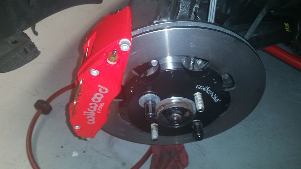
Bleeding the brakes, even with a Motive bleeder requires several stages to get a hard pedal.
I recommend bleeding all brakes. I start with the drivers side rear caliper, then to the passengers side rear caliper. Move over to the passenger side front caliper, and then the drivers side front caliper. Open each bleeder valve once you have a plastic tube over the end, and this tube is immersed in brake fluid. Open each valve, then close it after a few seconds, then reopen it and repeat until no bubbles of air are coming out. In my case, I still had to have my daughter in the car, with the engine on, pressing down on the brakes while I bled the brakes (after the 2nd Motive bleed) to get all of the air out. Put your wheels back on, torque the wheel nuts to 100 ft-lbs, and go for a ride to bed your brakes.
These Wilwood brakes are indeed a step up from the OEM brakes. I hope the polymatrix brake pads do not dust up as much as the OEMS.
I ordered a set of pads for the rears from Rockauto, but they still have not arrived. I may cancel the order and purchase some aftermarket ones.
I used the 3 day weekend to install my Willwood big brake kit with polymatrix pads. I got this kit several months ago, but had some problems getting the right Motive brake bleeder kit for the Fiesta ST. The correct numbers are 1108 or 1118 for the kit or just the adapter. The instructions that come with the Wilwood kit are good, but the photos are really small. There are very few bolts that need to be removed from the OEM brakes to allow for the installation of the BBK.
This is what the brake kit consists of:

Two rotors
Two rotor hub
Two calipers, one LH and the other RH
Two rotor "shims" that go underneath the rotor on the hub
Two hub to caliper brackets
Assorted fasteners to mate the rotor to the rotor hub. These are star fasteners, so you will need a good T40 wrench. I used a 3/8" drive for my torque wrench, and various sockets for attaching the brackets, the calipers. I used a 1/2" torque wrench for these larger bolts. Wilwood provides the torque requirements for these fasteners.
Important, you will need a 1/4" and 5/32" combination wrench to bleed the front and rear brakes. I also purchased a gemini brake bleeder bottle, but you could use an empty soda bottle. I also had a 1 liter can of Dot 4 ATE blue brake fluid. You will need a tygon tube to assist in bleeding the brakes.
Taking the OEM brakes off is really easy, especially since you won't need to put them back on. I removed the bolt for the slider pin, and this allowed me to rotate the caliper out of the way. The pads either stay in place or come along for the ride.


There are two bolts on the backside of the hub which connect the caliper to the hub. Remove these and the caliper bracket comes right off.
There is a 10mm bolt holding on the brake line to the strut. Remove this bolt and set it aside. I placed the caliper on a box to relieve the strain on the brake line.
Now, this is important, get a piece of hose that will fit over the hard brake line BEFORE you unscrew the hard brake line from the soft brake line. I used a piece of tygon tubing with a rubber plug on the end of it. You do not want to lose too much brake fluid, especially since as fluid goes out, air can get in.

There is a forked brake clamp that holds the OEM brake line to the frame. It has a hole at the end. I used a screwdriver and pair of pliers to remove it. The OEM caliper is now removed. I put it and its brother aside, inside of a plastic tray to allow the brake fluid to come out. Do not get brake fluid on your paint. If you do, rinse it with clear water. I used Isopropyl alchol, as it will cut the fluid faster when it get on the floor.
Getting your rotors off requires a dead blow plastic hammer, with lots of rotation.

You need to assemble your rotors. The hard part is torquing the star fasteners to connect the hat to the rotor. I placed masking tape on the rotor hat (to protect it from scratches) and placed it on the hub so that the hat faces the hub, and the fasteners can now be torqued to 25 ft-lbs in a star pattern. I placed a large screw driver into the rotor and rested the end on my knee, to prevent the rotor from turning. I assembled both rotors this way (Sorry, no pics).
I found that the OEM shield interfered with the rotor, so 3 screws and it was off. I also cleaned the hub and made sure there were no burrs and that the rotor fit flush against each hub. I used an angled air grinder with scotchbrite pads to clean up this surface of the hub.
Next place the bracket on the hub, making sure you have the bracket nuts that protrude out of the bracket facing the rotor. Fasten these on, making sure there is a flush fit, then pull one bolt at a time, apply red loctite, and torque these down. I believe its 70 ft-lbs, but I don't have the installation pamphlet with me, as I write this.
Then the adapter (centering device) is placed between the hub and the rotor, and the rotor is placed on the hub. There are no circlips to hold the rotor. Wilwood suggests using three wheel nuts, but I found that if you use a couple of washers between the rotor hat and the wheel nuts, it holds down the rotor fine.
There is a LH and a RH caliper, You will know that you have installed the correct caliper if the largest caliper piston is located at the lower part of the caliper as installed. You will need to add shims to center the caliper on the rotor. I used one .032 shim on each bolt for the passengers side, and two .032 shims on the drivers side for each bolt. Again, you pull each bolt, one at a time, apply red loctite, and torque them down, I believe its 40 ft-lbs.
Then the hardware for the brake line needs to be assembled. Using hydraulic wrenches, put the line together so that it resembles the OEM line. There is a brass 90 deg fitting that attaches to the back of the caliper. Attach the pipe thread end to the caliper, and the hydraulic fitting end to the line that came with the kit. There is a bracket that comes with the kit to allow one to attach the brake line to the strut. It comes with a grommet which needs to be forced around the brake line. I used a copper tube slightly larger than the line, and using lots of silicon lube (you can also use vaseline), forced the rubber grommet over the line and onto the center of the line. Then I slipped it into the bracket, and fastened it onto the strut.
The part of the brake line that fits to the hard line next needs to be assembled. Once this is assembled, insert the fitting through the bracket, and using the supplied forked clamp, attach this line to the frame. I used an 11/16 wrench to hole this line while I attached the hard brake line to the hose.

Bleeding the brakes, even with a Motive bleeder requires several stages to get a hard pedal.
I recommend bleeding all brakes. I start with the drivers side rear caliper, then to the passengers side rear caliper. Move over to the passenger side front caliper, and then the drivers side front caliper. Open each bleeder valve once you have a plastic tube over the end, and this tube is immersed in brake fluid. Open each valve, then close it after a few seconds, then reopen it and repeat until no bubbles of air are coming out. In my case, I still had to have my daughter in the car, with the engine on, pressing down on the brakes while I bled the brakes (after the 2nd Motive bleed) to get all of the air out. Put your wheels back on, torque the wheel nuts to 100 ft-lbs, and go for a ride to bed your brakes.
These Wilwood brakes are indeed a step up from the OEM brakes. I hope the polymatrix brake pads do not dust up as much as the OEMS.
I ordered a set of pads for the rears from Rockauto, but they still have not arrived. I may cancel the order and purchase some aftermarket ones.
Looking good man! I find it interesting that the Wilwood kit I just installed uses a different caliper. I had to wait close to 2 months for my kit as they has to manufacture more calipers. I'm curious as to what exactly is different....You have any info on this?
Photo of the caliper that came with my kit for reference:
 FiST - Willwood-2612 by T_Forde, on Flickr
Photo of the caliper that came with my kit for reference:

Thread Starter
#104
No idea, honestly, other than you have two fewer bleed ports. I can bleed my calipers without taking the wheels off. Yours looks a little thinner than mine, but that may just be camera angles.
Thread Starter
#106
I'll trade you!!! You are going to need extra stopping power now that you have so much more go power. I got some Brembos I gotta put on my 2011 mustang for the same reason!!! Stopping from 120 MPH in a single piston set up is plenty scary. I gotta order wheels and tires first.
I have all of the raamat and ensolite I need for my next project (Thanks Rick). I also got some closed cell foam with aluminum one side backing from work, and will be using it for my 2J Racing intake mod. I already received the JMR plug extension. After that, the IC and front crash bar from Dead Hook is on the list, followed up by the Wilwood BBK. Somewhere in between this stuff, I will finally install my flex fuel gage in my glovebox. And I'll have to move my OCC to where the Mountune airbox used to sit. I'm thinking of using a 5/8" copper U-bend to change the hose direction into the intake manifold. I want to keep the engine cover, but that may need to go away, based on where these hoses need to go.
Thread Starter
#108
Not yet. I just got the 2J Racing intake last week. I'm planning on putting the flex fuel gauge and sender along with the intake this weekend. I'll post my how to next Sunday. Then I'm going to install my Deadhook IC and crash bar the following week.
Thread Starter
#109
What with my Birthday on the 15th and Fathers day this last weekend, I wasn't able to get anything done, but being with the family has its own rewards. Plus I got some cool tools. I'm hoping the temps go down this next weekend, so I can work on my FiST and get the intake and the ethanol gauge installed. I still plan on making baffles and insulating the cowl area, and taking photos for this build.
Then the FMIC and crash bar the following weekend.
Then the FMIC and crash bar the following weekend.
Thread Starter
#110
OK This weekend I decided to tackle three different projects:
Install the 2J Racing intake (AKA the vacuum cleaner). This means I removed the Mountune air box and inlet silicone duct.
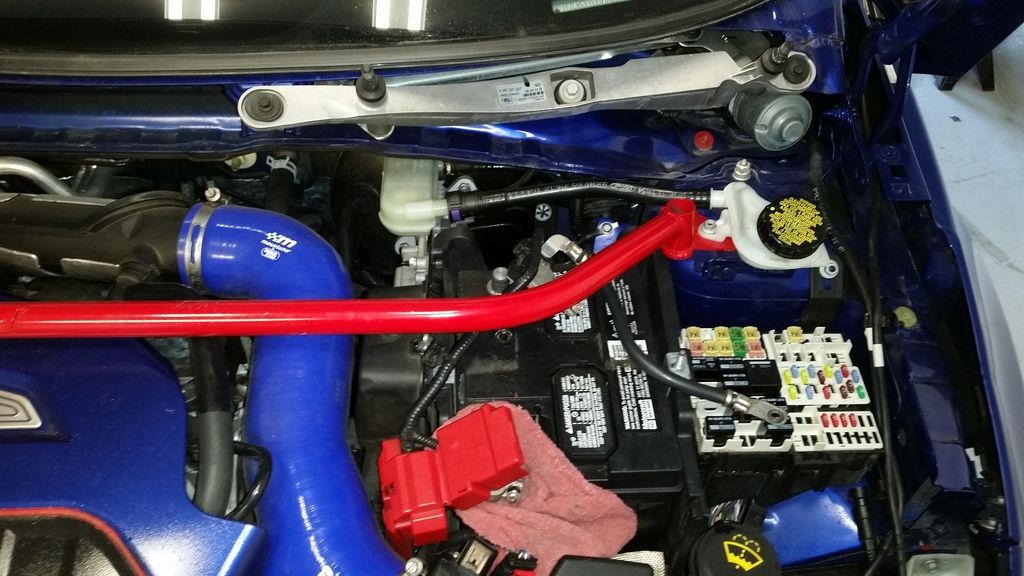
This also means I needed to relocate my Mishimoto OCC. That was project #2
Project #3 was to install the Razorlab Flex fuel ethanol percentage gauge.
The 2J Racing intake took the longest because there were some modifications I wanted to make. This required getting some 90 deg. elbows as well as 3 ft of 10 mm ID silicone hose. I already had the MAF extender.
Installing the intake has been discussed several times, so I won't go into detail on what is necessary to fit this intake. I did not like the angle or bend that the large silicone tube makes when it is installed. I had some 3/4" 90 deg. elbows that I used to make the route from the engine to the intake a more "natural" route.
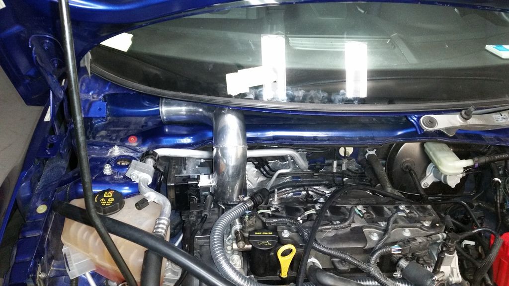
I made a cardboard template and mocked up a baffle that sits between the 2JR intake/air filter and the AC inlet. Here is what the aluminum part looked like before I put insulation on both sides on the baffle.
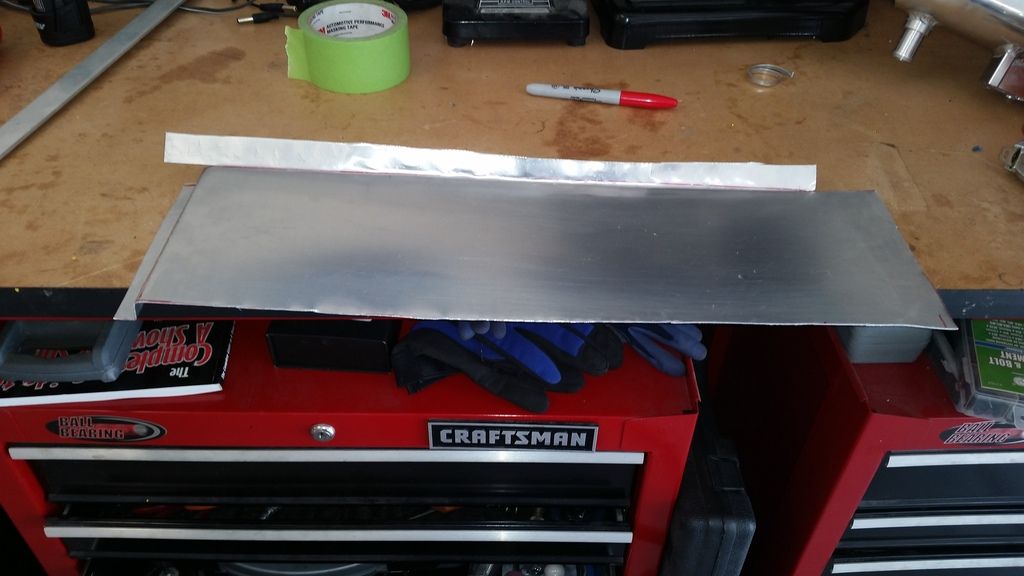
The baffle is flush on the left side of the AC vent and flares out to the right side, approx. 21" long to create an air path for the AC vent.
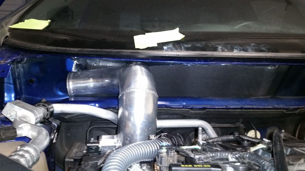
This is what the baffle looks like, installed. I used aluminum tape to seal the top of the baffle at the flange I made. The baffle is made of 1100 series aluminum which is very pliable, this also means its easy to form and shape. The next step was to attach the air filter to the intake.
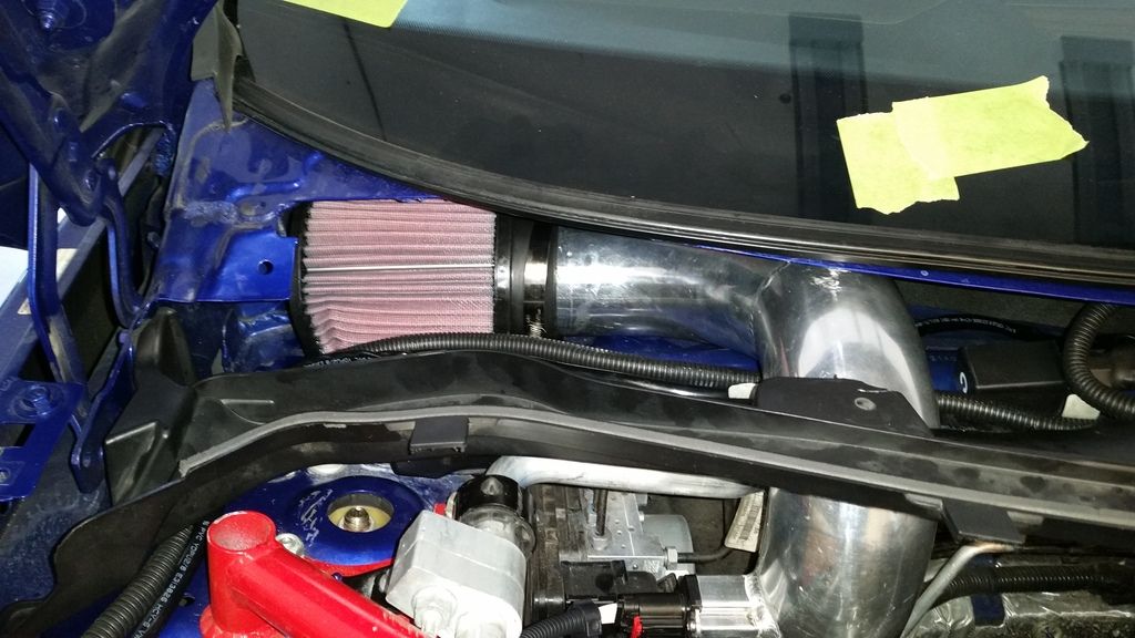
I put a breathable filter cover, also from K&N, but forgot to take a photo of that.
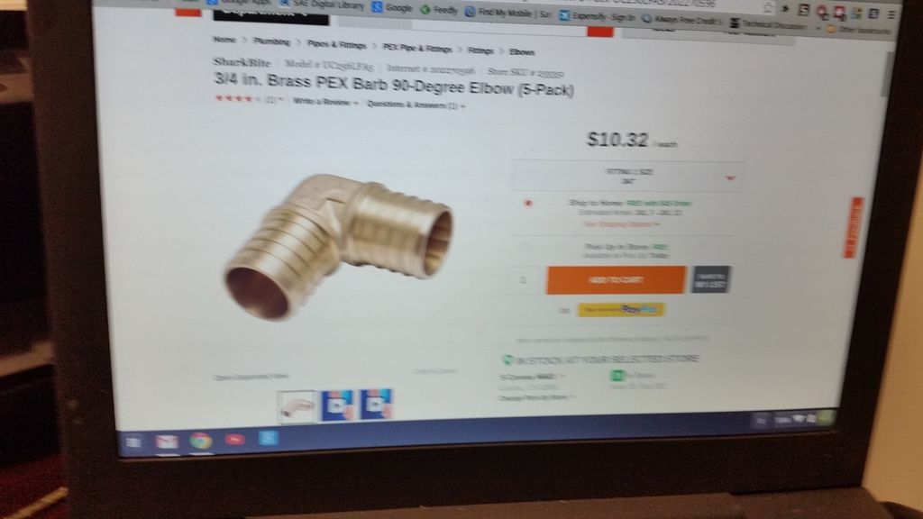
After installing the 2JR intake and clamping down the air filter, which is a PITA, I connected the MAF extension, and the large 3/4" silicone tube. I used some plastic 90 deg. elbows I had laying around. I think Ill replace them with some brass ones to account for underhood temps. Home depot has them in stock.
This is what the 3/4" silicone tube looks like.
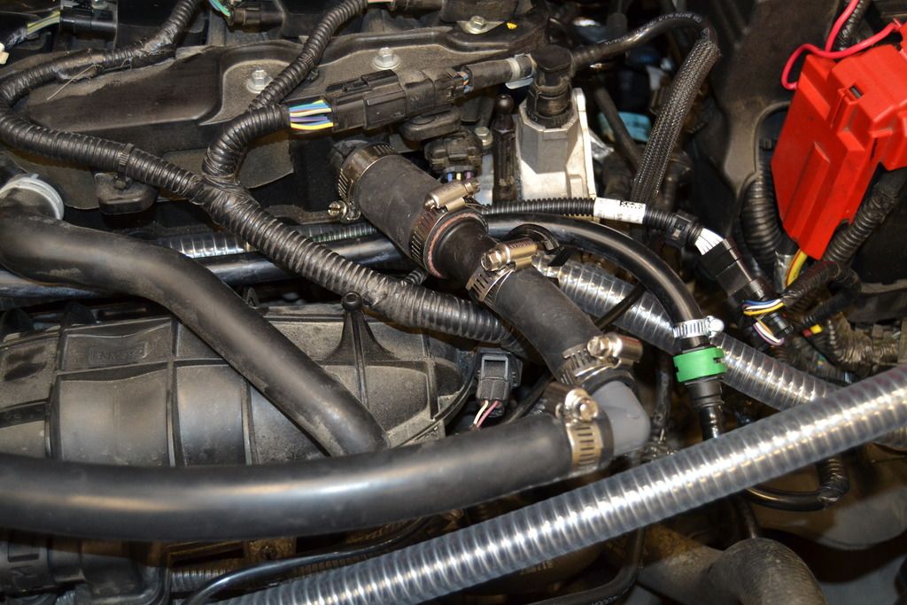
The kit comes with a smaller silicone hose that looks like a 5 or 6mm ID. I didn't want to force the hose onto the nipple, so I ordered a 10mm ID silicone hose from Amazon. The only necessary addition is a hose clamp on the supplied fitting, as shown above.
Then comes the trimming of the lower cowl. I tried to leave a 10 mm gap between all plastic surfaces and the aluminum intake. after that you just button up the upper cowl, replace the front Pierce motorsports strut brace. and your done.
I also pulled the battery after I pilled fuse #11 in the engine bay and ran the engine until it ran out of gas.
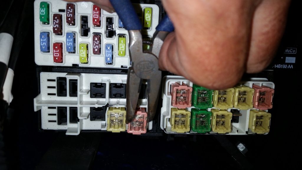
Note, the How to's say to pull fues 1. That is not the correct fuse. Pull fues 11.
Pulling this fuse and running the engine dry is to be able to mount the flex fuel hardware.
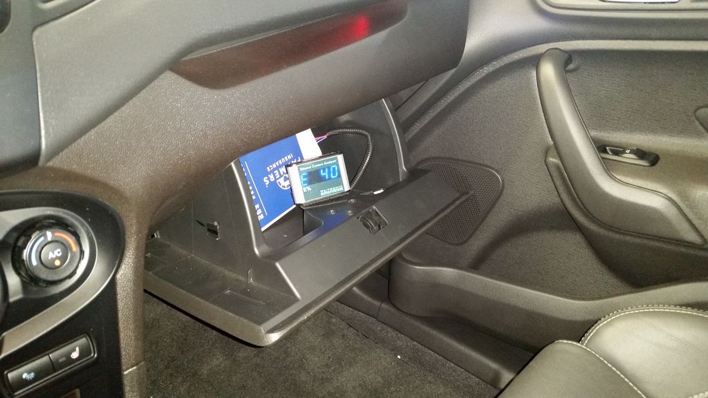
Last month, I decided to modify the Zeitronix gauge so that the wires came out of the back of the gauge. It comes out of the bottom as shipped. There are two screws at the bottom of the gauge. Remove these and slide out the display.
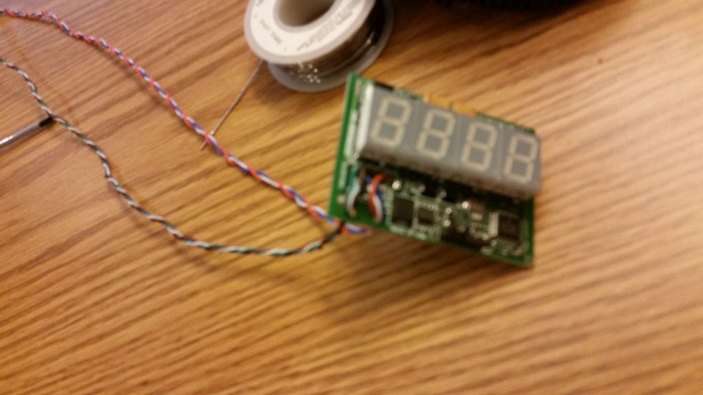
You need to reroute the wires to the back of the display. Then drill a hole in the back of the aluminum case, and then seal up the hole in the bottom.
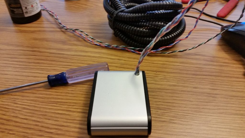
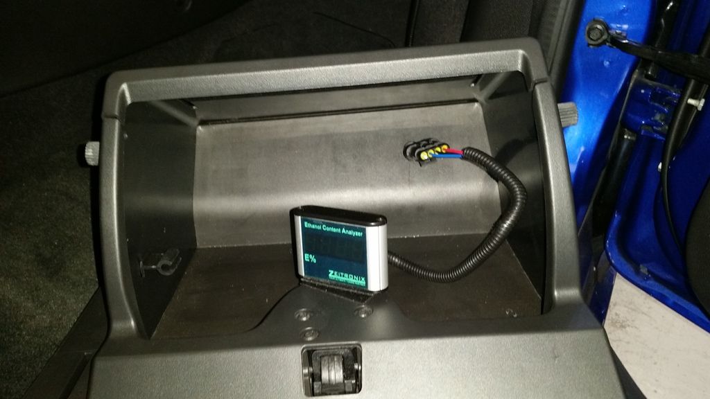
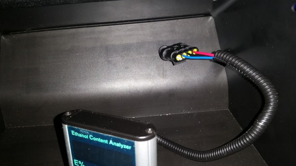
I placed the wires into a split wire cover and used liquid tape to make a strain relief/grommet for the wires coming out the back of the flex fuel gauge. I wanted the wires coming out of the back so I could place Velcro and attach the gauge to the glovebox.
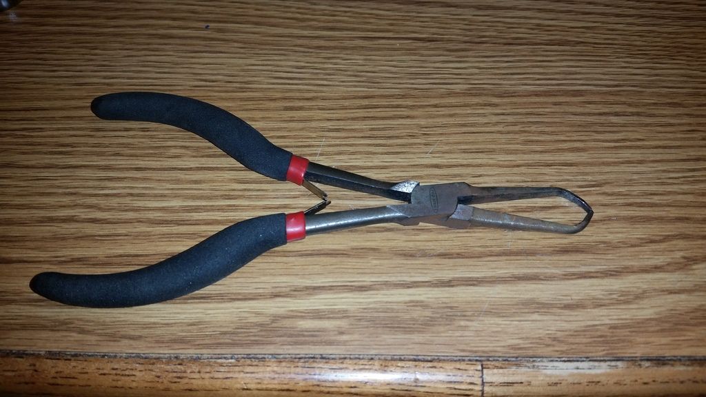
I made a tool to pull the gas line out, this was a long nose plier that I bent the ends so I can push the two "buttons" on the fuel line.
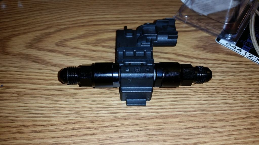
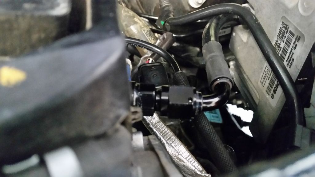
Next, I mounted the fittings on the Chevrolet fuel sensor. I used open box end wrenches for a better grip.
In order to mount the other fittings on the existing fuel lines, I disconnected and slid out the stainless steel line that is attached to the engine, and tightened the fitting.
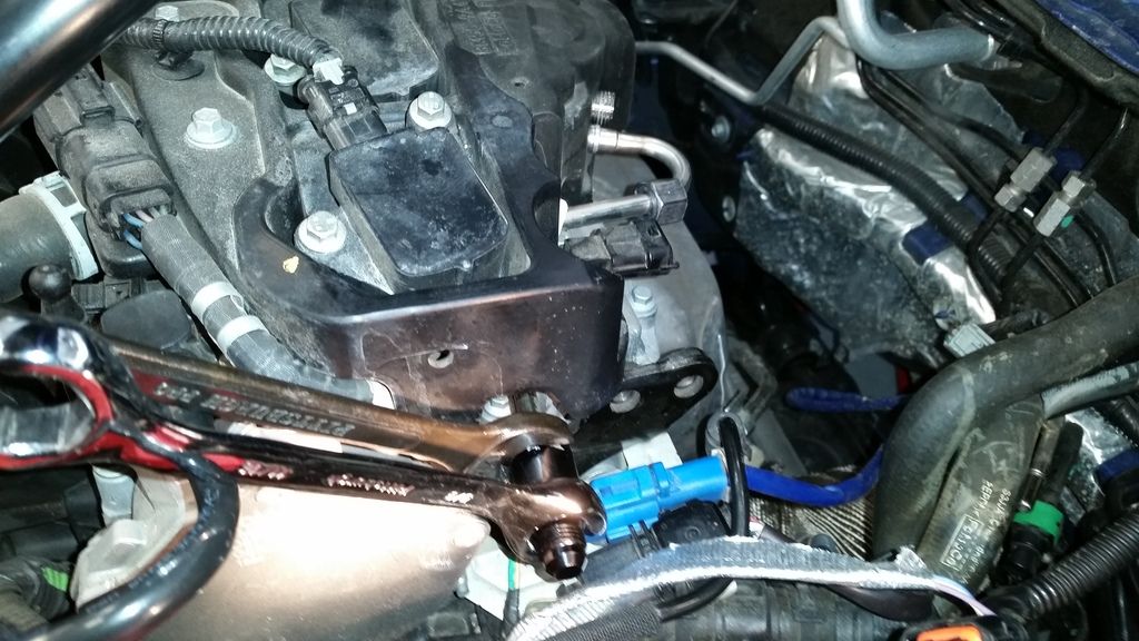
I attached the other fitting to the hard line near the firewall. You can see the wrenches, but not really the fitting.
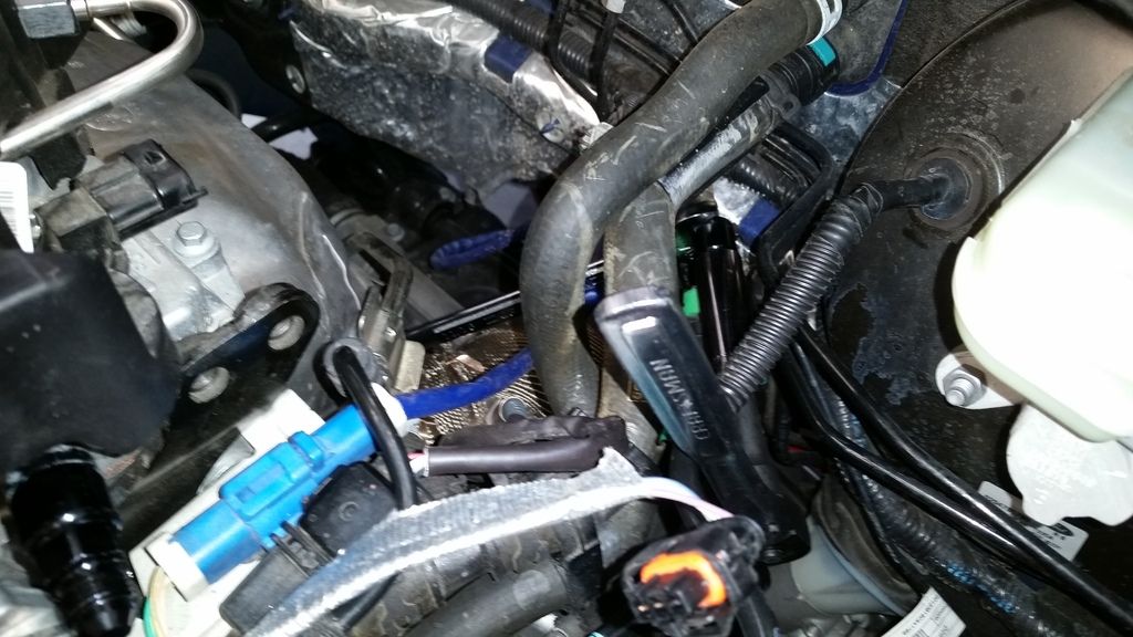
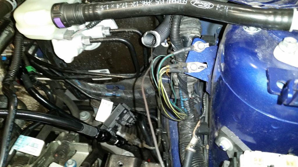
Then I attached the two hoses to the flex fuel sensor, and then to the hard lines and tightened everything down securely.
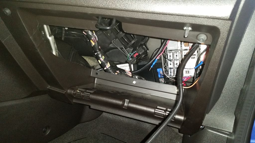
I routed the sensor line through the symposer tube. I attached a length of wire to the sensor wires with electrical tape and fished the line through to the inside of the drivers side. Then over to the glove box.
I punched a hole into the back of the glove box and using two sets of four wire connectors, set up the gauge so I could disconnect the gauge from the glove box or separate the glove box from the wiring that connected to the sensor, ground and fuse #8 (moon roof). All connections were soldered and covered with shrink tube, then split wire covers to make everything look OEM. Here are some photos.
Install the 2J Racing intake (AKA the vacuum cleaner). This means I removed the Mountune air box and inlet silicone duct.

This also means I needed to relocate my Mishimoto OCC. That was project #2
Project #3 was to install the Razorlab Flex fuel ethanol percentage gauge.
The 2J Racing intake took the longest because there were some modifications I wanted to make. This required getting some 90 deg. elbows as well as 3 ft of 10 mm ID silicone hose. I already had the MAF extender.
Installing the intake has been discussed several times, so I won't go into detail on what is necessary to fit this intake. I did not like the angle or bend that the large silicone tube makes when it is installed. I had some 3/4" 90 deg. elbows that I used to make the route from the engine to the intake a more "natural" route.

I made a cardboard template and mocked up a baffle that sits between the 2JR intake/air filter and the AC inlet. Here is what the aluminum part looked like before I put insulation on both sides on the baffle.

The baffle is flush on the left side of the AC vent and flares out to the right side, approx. 21" long to create an air path for the AC vent.

This is what the baffle looks like, installed. I used aluminum tape to seal the top of the baffle at the flange I made. The baffle is made of 1100 series aluminum which is very pliable, this also means its easy to form and shape. The next step was to attach the air filter to the intake.

I put a breathable filter cover, also from K&N, but forgot to take a photo of that.
After installing the 2JR intake and clamping down the air filter, which is a PITA, I connected the MAF extension, and the large 3/4" silicone tube. I used some plastic 90 deg. elbows I had laying around. I think Ill replace them with some brass ones to account for underhood temps. Home depot has them in stock.

This is what the 3/4" silicone tube looks like.

The kit comes with a smaller silicone hose that looks like a 5 or 6mm ID. I didn't want to force the hose onto the nipple, so I ordered a 10mm ID silicone hose from Amazon. The only necessary addition is a hose clamp on the supplied fitting, as shown above.
Then comes the trimming of the lower cowl. I tried to leave a 10 mm gap between all plastic surfaces and the aluminum intake. after that you just button up the upper cowl, replace the front Pierce motorsports strut brace. and your done.
I also pulled the battery after I pilled fuse #11 in the engine bay and ran the engine until it ran out of gas.

Note, the How to's say to pull fues 1. That is not the correct fuse. Pull fues 11.
Pulling this fuse and running the engine dry is to be able to mount the flex fuel hardware.
Last month, I decided to modify the Zeitronix gauge so that the wires came out of the back of the gauge. It comes out of the bottom as shipped. There are two screws at the bottom of the gauge. Remove these and slide out the display.

You need to reroute the wires to the back of the display. Then drill a hole in the back of the aluminum case, and then seal up the hole in the bottom.

I placed the wires into a split wire cover and used liquid tape to make a strain relief/grommet for the wires coming out the back of the flex fuel gauge. I wanted the wires coming out of the back so I could place Velcro and attach the gauge to the glovebox.
I made a tool to pull the gas line out, this was a long nose plier that I bent the ends so I can push the two "buttons" on the fuel line.

Next, I mounted the fittings on the Chevrolet fuel sensor. I used open box end wrenches for a better grip.

In order to mount the other fittings on the existing fuel lines, I disconnected and slid out the stainless steel line that is attached to the engine, and tightened the fitting.

I attached the other fitting to the hard line near the firewall. You can see the wrenches, but not really the fitting.

Then I attached the two hoses to the flex fuel sensor, and then to the hard lines and tightened everything down securely.

I routed the sensor line through the symposer tube. I attached a length of wire to the sensor wires with electrical tape and fished the line through to the inside of the drivers side. Then over to the glove box.

I punched a hole into the back of the glove box and using two sets of four wire connectors, set up the gauge so I could disconnect the gauge from the glove box or separate the glove box from the wiring that connected to the sensor, ground and fuse #8 (moon roof). All connections were soldered and covered with shrink tube, then split wire covers to make everything look OEM. Here are some photos.


Thread Starter
#114
Well, I installed the DHM intercooler this weekend and all I can say is WOW. This intercooler is a great improvement over the stock Intercooler, especially at higher temperature ranges. I have done extensive logs before and after the DHM IC install and the difference can be as much as 30 deg. F. Sorry to say that these same logs showed that the 2JR intake is not better that the mountune box and intake, and in some cases is even worse. This is only true when the car has been sitting all day in the heat at my place of business in Los Alamitos. In the morning, the 2JR cowl intake works great.
It turns out that the cowl compartment reaches 116F vs 92F for the mountune box when I leave work at about 2:30 PM. Both setups were covered with "gold" dissipating tape, so as to be comparing apples to apples. In the case of the mountune box, only the box is covered with this gold tape. Since I put the mountune box and intake back in, I relocated the Mishimoto catch can back where it was originally, attached to the passenger's side strut housing. This turns out to be the optimum placement for this universal catch can. I also plugged up the hole in the lower plastic cowl that I cut up when installing the 2JR intake.
I'll be selling the 2JR intake along with a few shifter knobs, the Boomba short shift lever assembly and aluminum shift base bushings, both the shifter and bushings never installed. Most likely as a boomba package with the boomba shift know, shift lever and bushings.
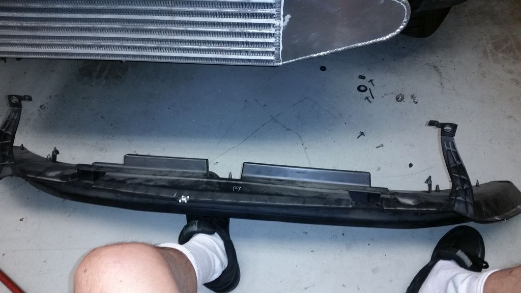
I really didn't take any photos of the IC install, since it is identical to my Levels install, just a whole lot bigger. I use Murray turbo clamps, so when I sell the Levels IC, it will come with 4 turbo clamps, a $28.00 value. These clamps work so much better than the OEM ones or the T-Bolt clamps, they're the only type I'll ever use, especially if I go to a bigger turbo.
One item to note. There are two dog legged brackets that attach to the bottom of the radiator, with either the Levels IC or the OEM IC, these do not get reused with the DHM IC. Leave these off. Also with the Mountune hoses, in order to make them fit flush against the IC pipe, you need to slightly twist them towards the IC, then tighten down the clamps. This way the install properly. I really didn't use any of the DHM fasteners, as they are hex head. I really like using stainless steel button head, allen head fasteners with stainless steel, locking nuts. I purchased an assortment of these nuts and bolts of different lengths and thread diameters (6, 7, 10 12 mm). I think they look better, and are corrosion resistant.
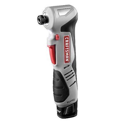
A tool that I use which I swear by is a Craftsman nextec right angle impact driver. This is a light weight, small profile nut driver that is perfect for getting into tight places.
I also purchased a security bit tool kit consisting of multiple hex, allen, and safety bits, as well as adapters for using 1/4 inch drive sockets along with with the nextec driver. I purchased this from Amazon for 12.99. This is the Neiko 100 pc security bits set.
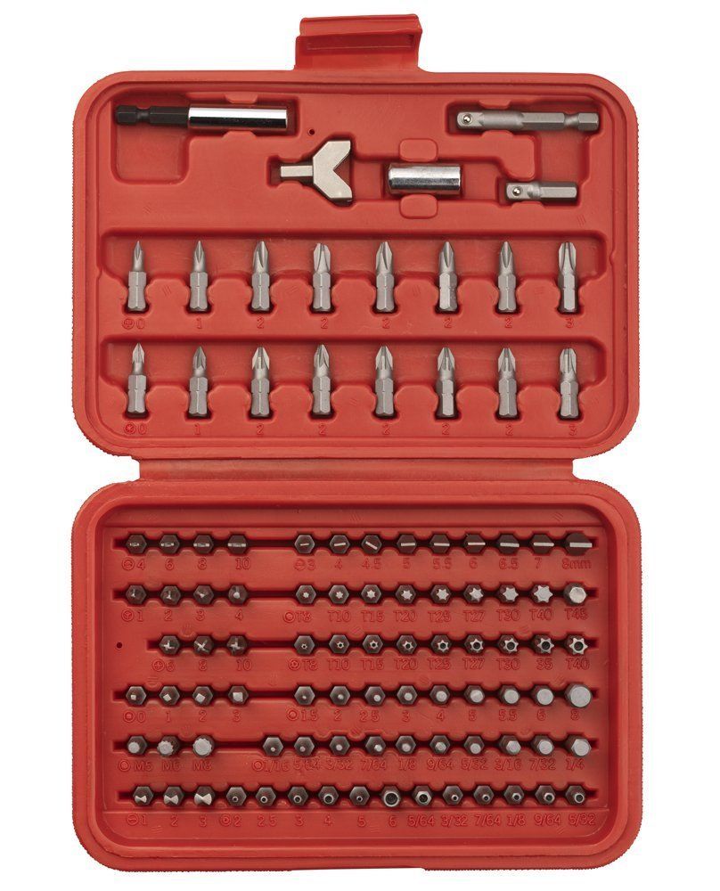
This kit, along with the Craftsman Nextec, and the batteries and charger can also be used as a drill, with the proper bits that contain nut driver ends.
This kit came in handy when tightening the boost clamps when I replaced the OEM plastic hose that routes to the Mountune inlet and air box.
When I had the front clip off, I drilled a hole with a hole saw and added a 3" PVC tube to route air to the snorkle in the Mountune air box. I'll take some pics of this installation and the IC.
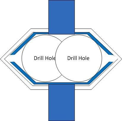
Another thing I did was to take some aluminum sheet and fasten it into a fixture to protect the honeycomb grill shape. I ended up using a step drill as a poor mans router, along with this jig, to drill out the honeycomb at the bottom end of the grille. This made a two to three hour process using a grinder from the back side, into a 10 minute process. The jig protected the side walls of the honeycomb, while I drilled two holes and joined them together with the step drill.
Here is a sketch of the jig, not to scale, or even correct, but you get the idea.
It turns out that the cowl compartment reaches 116F vs 92F for the mountune box when I leave work at about 2:30 PM. Both setups were covered with "gold" dissipating tape, so as to be comparing apples to apples. In the case of the mountune box, only the box is covered with this gold tape. Since I put the mountune box and intake back in, I relocated the Mishimoto catch can back where it was originally, attached to the passenger's side strut housing. This turns out to be the optimum placement for this universal catch can. I also plugged up the hole in the lower plastic cowl that I cut up when installing the 2JR intake.
I'll be selling the 2JR intake along with a few shifter knobs, the Boomba short shift lever assembly and aluminum shift base bushings, both the shifter and bushings never installed. Most likely as a boomba package with the boomba shift know, shift lever and bushings.
I really didn't take any photos of the IC install, since it is identical to my Levels install, just a whole lot bigger. I use Murray turbo clamps, so when I sell the Levels IC, it will come with 4 turbo clamps, a $28.00 value. These clamps work so much better than the OEM ones or the T-Bolt clamps, they're the only type I'll ever use, especially if I go to a bigger turbo.
One item to note. There are two dog legged brackets that attach to the bottom of the radiator, with either the Levels IC or the OEM IC, these do not get reused with the DHM IC. Leave these off. Also with the Mountune hoses, in order to make them fit flush against the IC pipe, you need to slightly twist them towards the IC, then tighten down the clamps. This way the install properly. I really didn't use any of the DHM fasteners, as they are hex head. I really like using stainless steel button head, allen head fasteners with stainless steel, locking nuts. I purchased an assortment of these nuts and bolts of different lengths and thread diameters (6, 7, 10 12 mm). I think they look better, and are corrosion resistant.

A tool that I use which I swear by is a Craftsman nextec right angle impact driver. This is a light weight, small profile nut driver that is perfect for getting into tight places.

I also purchased a security bit tool kit consisting of multiple hex, allen, and safety bits, as well as adapters for using 1/4 inch drive sockets along with with the nextec driver. I purchased this from Amazon for 12.99. This is the Neiko 100 pc security bits set.

This kit, along with the Craftsman Nextec, and the batteries and charger can also be used as a drill, with the proper bits that contain nut driver ends.
This kit came in handy when tightening the boost clamps when I replaced the OEM plastic hose that routes to the Mountune inlet and air box.
When I had the front clip off, I drilled a hole with a hole saw and added a 3" PVC tube to route air to the snorkle in the Mountune air box. I'll take some pics of this installation and the IC.
Another thing I did was to take some aluminum sheet and fasten it into a fixture to protect the honeycomb grill shape. I ended up using a step drill as a poor mans router, along with this jig, to drill out the honeycomb at the bottom end of the grille. This made a two to three hour process using a grinder from the back side, into a 10 minute process. The jig protected the side walls of the honeycomb, while I drilled two holes and joined them together with the step drill.
Here is a sketch of the jig, not to scale, or even correct, but you get the idea.

Thread Starter
#115
I kind of dropped the ball on my build list and didn't take any photos of my work to date. Here is what has been installed so far.
I went ahead and purchased two additional Pierce Motorsports suspension parts. The rear torsion bar and the lateral rear trunk brace. I didn't take any photos of this install because the install was relatively simple and straightforward. The rear torsion bar needs to be setup and hit with a dead blow hammer to get it into place so it lines up with the holes in the flex bar. The rear trunk brace requires some trimming of the plastic end covers, so that they fit properly. I used a step drill bit and then a dremel with a drum sanding roll to finish out the relief I put into these end caps.
I had my first part installed by someone other than me, which was nerve racking to say the least, since I usually do all my own work on my FiST. I had a bout with middle back problems, so I decided to go with Mod Auto to install my BC coilovers that I purchased from 2JR during their christmas sale. The coilovers were installed without any problems, and after the suspension settled, I had them align the front end. I dropped the front about 3/4" and the back about 1". I also had to replace my front splitter when I ran into a big piece of semi tire carcass that tore up my front clip. My insurance paid for replacement parts. Joey at the Ford dealer (Fritts Ford) even ground down the back of my grille so that it matched the one I did, and gave me the old grille. I'm planning on getting some wire mesh from a place like Zunsport and fitting it to the grille surround from my old front end, just to see if it looks like the European grill retrofit. I already checked, and the MK VII grille is shorter than the US spec grille so it will not fit. They do sell mesh grille. I plan on forming the grille, then getting it powdercoated black. I'll also install my blue Fiesta ST badge.
Next up is the Tune+ IWG install and the Velossa big mouth intake. I plan on taking pics and providing a complete install on my Mountune air box. Since I bent the heat shield when I installed my catted downpipe, I purchased a new heat shield and water hard tube so that I have these items ready to use when I install the internal wastegate from Tune+. Then I'll get some logs off to Adam. My back has finally healed and I'm itching to get this work done ASAP.
Thread Starter
#117
I also picked up a myfordtouch rear view camera kit from autotoys.com for $365.00 that interfaces with my touch screen. I also picked up a rear view camera from Amazon that will complete my package.
Thread Starter
#119
We definitely need more pictures!
That Craftsman 90° driver is slick - I need something similar...
That Craftsman 90° driver is slick - I need something similar...
Similar threads
-
-
Used performance parts- Both Tips Performance in Rock Hill South Carolina
- Started by Stevesims
- Replies: 7
-
MK8 Ford Fiesta ST performance service manual & maintenance intervals
- Started by fiestanewbie
- Replies: 4
-
How can I setup the ST performance display
- Started by ScaR
- Replies: 1
-
INTRODUCING - The Game Changer in Performance Braking!
- Started by MFactory
- Replies: 11
-
-
Wagner intercooler and TB performance crashbar
- Started by Ganjie
- Replies: 0
-
-
-
Ford Community Posts
-
-
Removed driver side blend door actuator without replacing it
- Latest: Sprinkle_Star
-
Clutch pedal sticking to the floor
- Latest: Sprinkle_Star
