-
Sign Up! To view all forums and unlock additional cool features
Welcome to the #1 Fiesta ST Forum and Fiesta ST community dedicated to Fiesta ST owners and enthusiasts. Register for an account, it's free and it's easy, so don't hesitate to join the Fiesta ST Forum today!
WestcoaST Performance blue build
- Thread starter westcoaST
- Start date
Thread Starter
#62
This weekend I installed my Triple R Splitter. There is a how to out there by Joe from 2J racing, but several steps were not clearly described, so I thought I'd do a little how to.
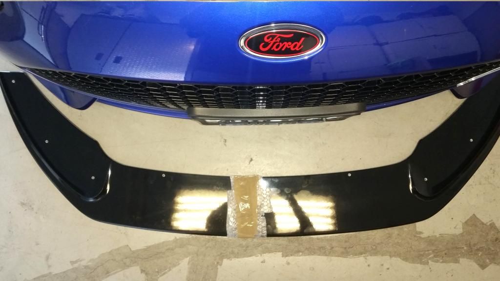
The fasteners that come with the splitter cannot really be used for the installation. I only used two of them. Secondly, locating the splitter is not completely described. Here are the steps I took. You will need some nylon or rubber spacers, approx. 40mm in thickness. I got some 90 durometer isolation rubber washers from Amazon. These are used with the two trim screws that attach the splitter to the bumper cover
1. Place your car up on jackstands. This makes it easier to move the wheels left and right to get to some of the fasteners.
2. There are two trim pieces that attach to the bumper cover. These are made from a soft synthetic rubber. Remove these for trimming later. There are several fasteners you need to remove here and under the bumper cover to remove the trim pieces.
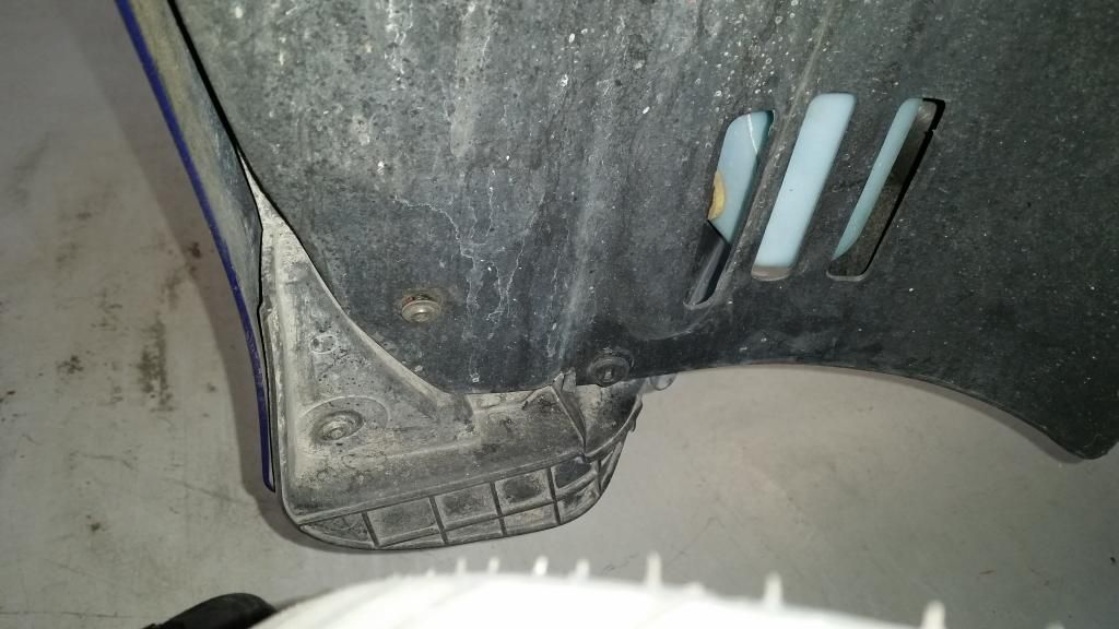
3. There are several holes that need to be drilled in the splitter to match up with several 40mm trim screws. Problem is, you need to locate these holes on the splitter. Here is how I did this.
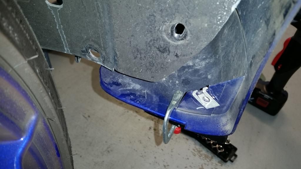
3a. Place tape on the bumper cover approximately locating the two holes on either side that you will be match drilling to. If you pull the wheel covers back, where you removed the trim pieces, you will see two captive nuts. These are the two locations you will need to match drill on the splitter. Remove the four trim screws and set them aside for later.
Here is a photo of one of the captive nuts. I had to partially remove and set aside both headlights to take this photo, your arms may be long enough that you don't need to.
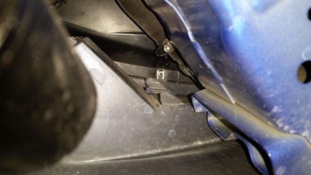
3b. Place paper masking tape on the splitter corresponding to the locations where the four captive nuts are on the bumper cover. Secure the splitter to the bumper cover, I used two small clamps and a bench with a piece of 2x4. Make sure you have the splitter located properly so the ends are flush with the bumper cover ends.
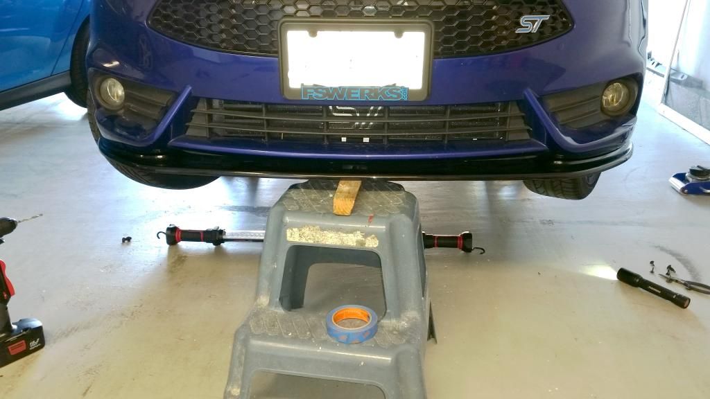
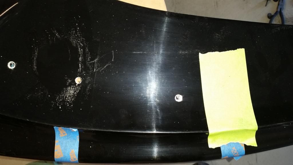
Here is what it looks like when you have tape on the bumper and splitter to get ready for match drilling. See the green tape on the splitter.
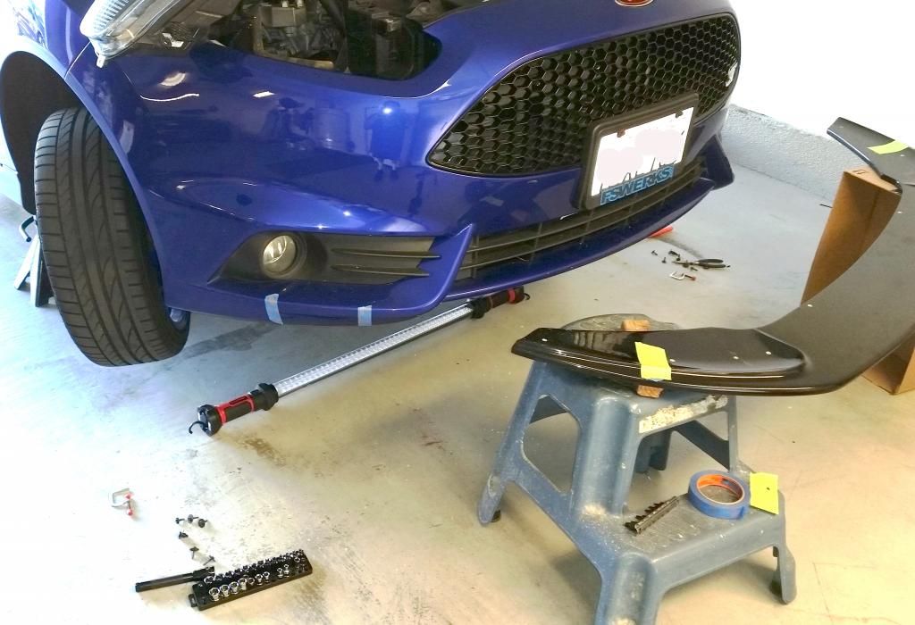
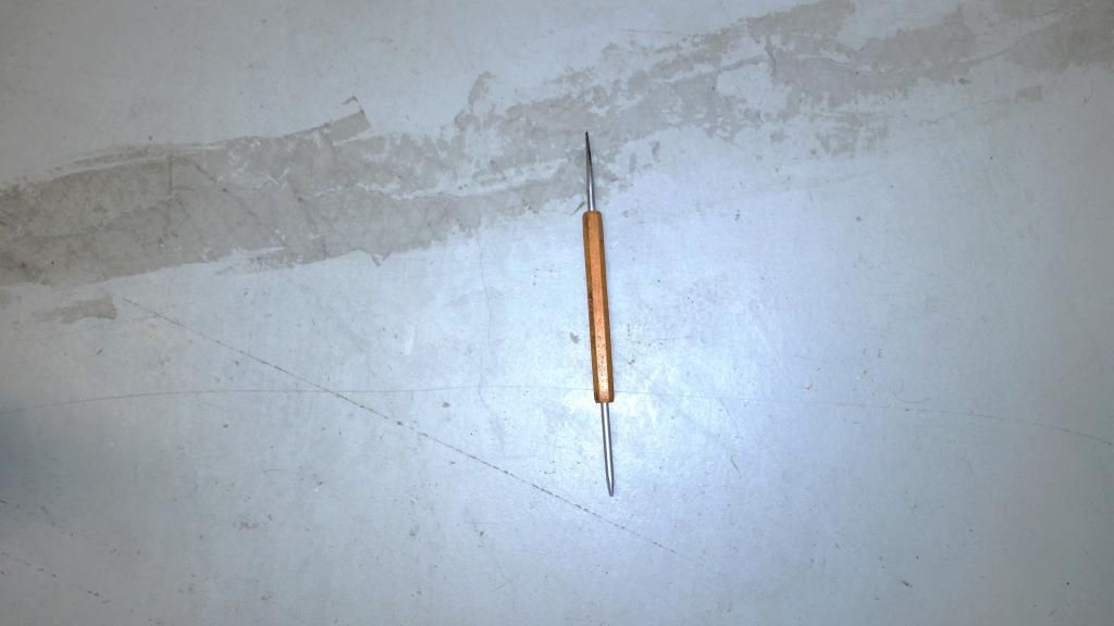
3c. With the splitter temporarily mounted with C clamps and the bench, take a thin, sharp object, and go through the inside of the bumper cover, place the sharp object through the center of the captive nut, in order to make a small hole on each of the pieces of paper tape. Remove the splitter, and here is what the tape will look like. There will be a small hole where you need to drill a 1/4" hole.

Here is the tool I used to make the holes in the paper tape.
Here is what one hole looks like after match drilling. I used a wood drill, the kind with a little point in the center, to locate the center of the drill, so it does not wander. The tape also helps with the drilling operation. Drill all four holes.
4. There is another trim screw that needs to be pulled from the bumper cover and match drilled. This one you have to measure out and drill. I used a CRES fender washer to distribute the load better.
5. Clamp up the splitter and install the four trim screws. I used fender washers to spread the load better than the smaller washers on the trim screws. Drill the two holes at the very end of the splitter, as shown in Joe's how-to. I used the two long allen head fasteners that came with the splitter, along with the washers. I used two 12mm CRES (stainless steel) locking nuts.
6. I had purchased 50mm long x 10mm x 1.5 CRES fasteners and CRES locking nuts, and some CRES washers from Bolt Depot to fasten the two already drilled holes in the back of the splitter to the two tabs on the bumper cover. I inserted the rubber washers in between the splitter and the bumper tabs and placed a locking nut on the fasteners, and cinched down the fasteners.
Thats all there is to it. Protect yourself from the fiberglass from the holes you need to drill. I used protective eyewear and Nitrile gloves. Sweep up any drilled fiberglass, so you don't roll around in it. Enjoy your new splitter.
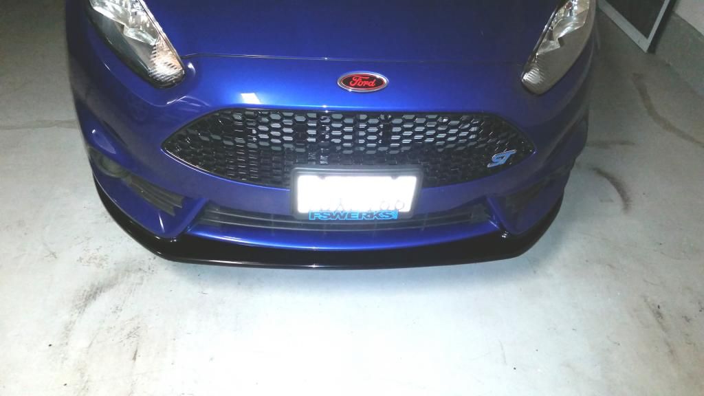

The fasteners that come with the splitter cannot really be used for the installation. I only used two of them. Secondly, locating the splitter is not completely described. Here are the steps I took. You will need some nylon or rubber spacers, approx. 40mm in thickness. I got some 90 durometer isolation rubber washers from Amazon. These are used with the two trim screws that attach the splitter to the bumper cover
1. Place your car up on jackstands. This makes it easier to move the wheels left and right to get to some of the fasteners.
2. There are two trim pieces that attach to the bumper cover. These are made from a soft synthetic rubber. Remove these for trimming later. There are several fasteners you need to remove here and under the bumper cover to remove the trim pieces.

3. There are several holes that need to be drilled in the splitter to match up with several 40mm trim screws. Problem is, you need to locate these holes on the splitter. Here is how I did this.
3a. Place tape on the bumper cover approximately locating the two holes on either side that you will be match drilling to. If you pull the wheel covers back, where you removed the trim pieces, you will see two captive nuts. These are the two locations you will need to match drill on the splitter. Remove the four trim screws and set them aside for later.
Here is a photo of one of the captive nuts. I had to partially remove and set aside both headlights to take this photo, your arms may be long enough that you don't need to.

3b. Place paper masking tape on the splitter corresponding to the locations where the four captive nuts are on the bumper cover. Secure the splitter to the bumper cover, I used two small clamps and a bench with a piece of 2x4. Make sure you have the splitter located properly so the ends are flush with the bumper cover ends.


Here is what it looks like when you have tape on the bumper and splitter to get ready for match drilling. See the green tape on the splitter.

3c. With the splitter temporarily mounted with C clamps and the bench, take a thin, sharp object, and go through the inside of the bumper cover, place the sharp object through the center of the captive nut, in order to make a small hole on each of the pieces of paper tape. Remove the splitter, and here is what the tape will look like. There will be a small hole where you need to drill a 1/4" hole.

Here is the tool I used to make the holes in the paper tape.

Here is what one hole looks like after match drilling. I used a wood drill, the kind with a little point in the center, to locate the center of the drill, so it does not wander. The tape also helps with the drilling operation. Drill all four holes.

4. There is another trim screw that needs to be pulled from the bumper cover and match drilled. This one you have to measure out and drill. I used a CRES fender washer to distribute the load better.
5. Clamp up the splitter and install the four trim screws. I used fender washers to spread the load better than the smaller washers on the trim screws. Drill the two holes at the very end of the splitter, as shown in Joe's how-to. I used the two long allen head fasteners that came with the splitter, along with the washers. I used two 12mm CRES (stainless steel) locking nuts.
6. I had purchased 50mm long x 10mm x 1.5 CRES fasteners and CRES locking nuts, and some CRES washers from Bolt Depot to fasten the two already drilled holes in the back of the splitter to the two tabs on the bumper cover. I inserted the rubber washers in between the splitter and the bumper tabs and placed a locking nut on the fasteners, and cinched down the fasteners.
Thats all there is to it. Protect yourself from the fiberglass from the holes you need to drill. I used protective eyewear and Nitrile gloves. Sweep up any drilled fiberglass, so you don't roll around in it. Enjoy your new splitter.

Thread Starter
#63
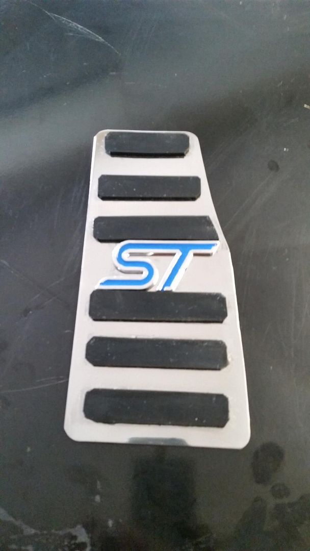
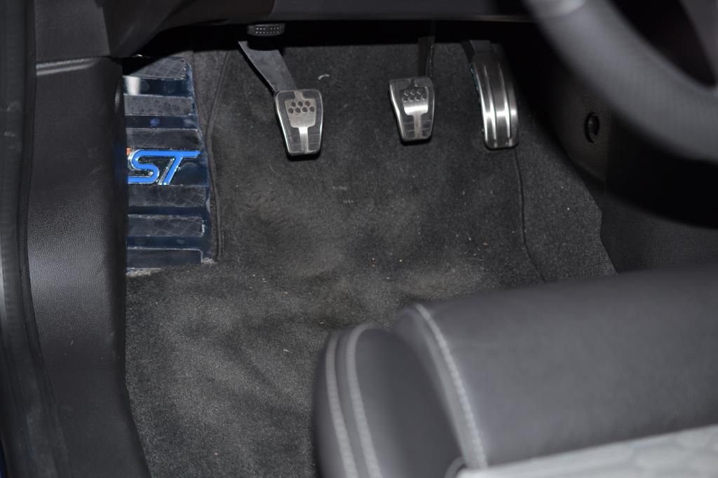
I made and installed a custom dead pedal out of a scrap piece of stainless steel. I took a piece of card board and cut it to match the dead pedal area, thed I transferred the outline of the card board to the stainless steel sheet, and cut the shape out with an abrasive disc grinder. I polished up the deal pedal and then installed a blue ST badge, purchased from Amazon, and attached it to the dead pedal. I also purchased a sheet of rubber, that I cut into several strips, and glued them down to the dead pedal.


Thread Starter
#64
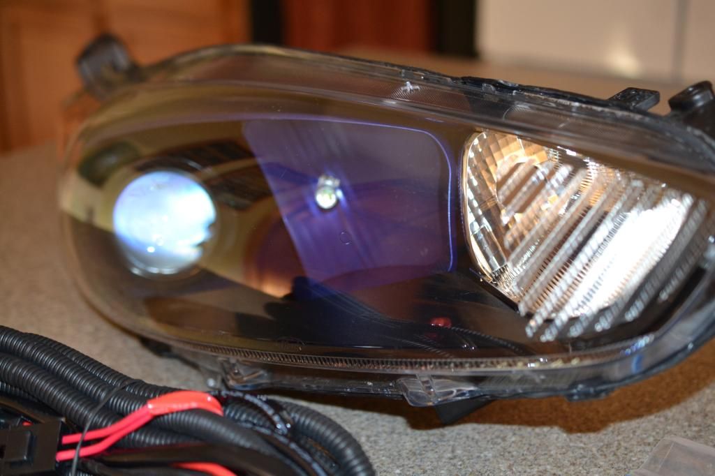
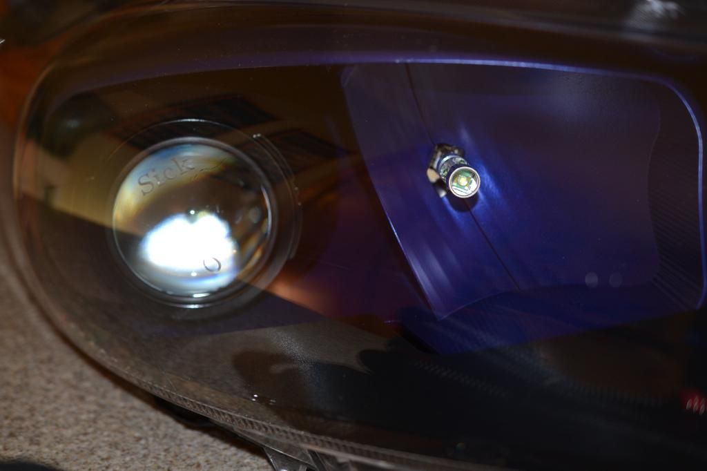
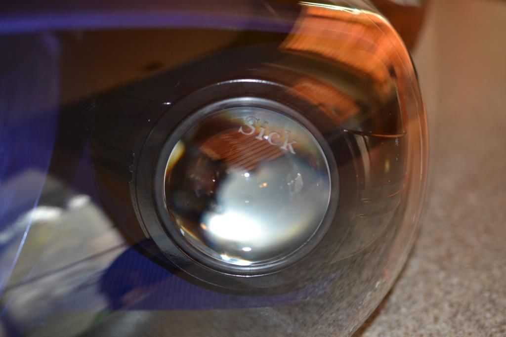
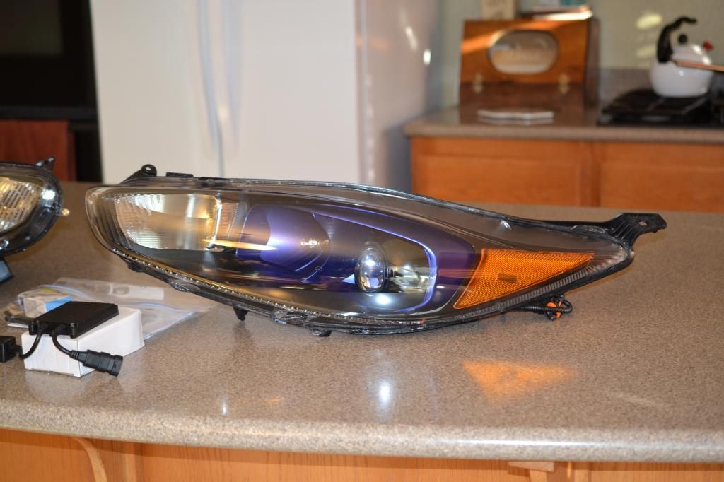
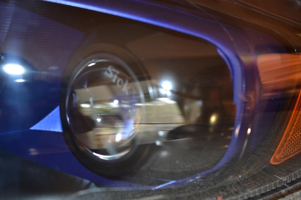
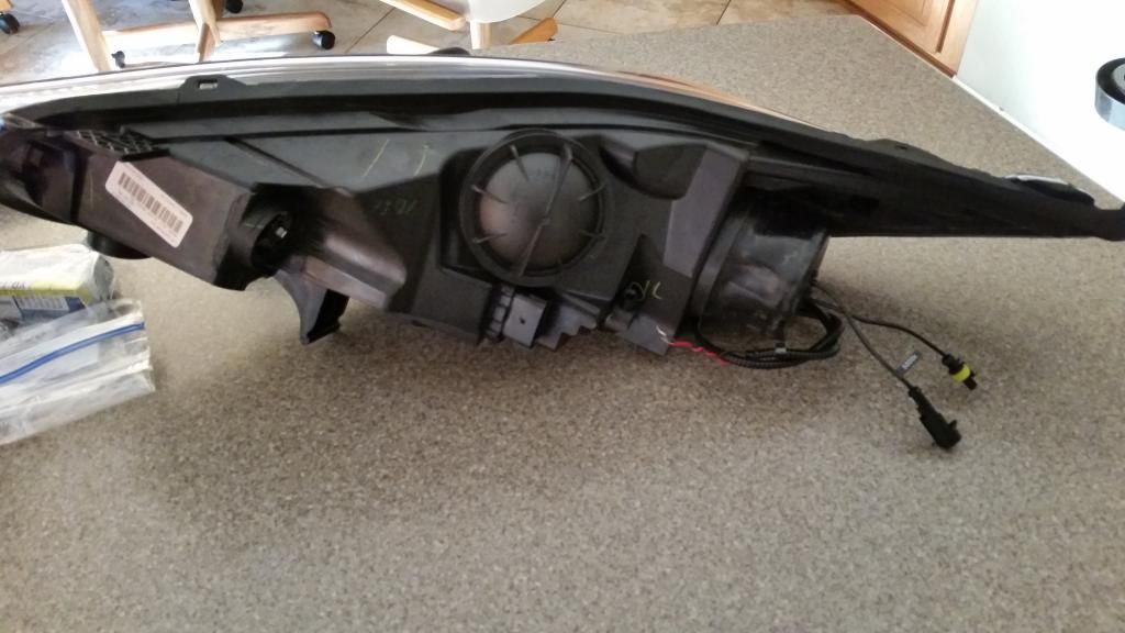
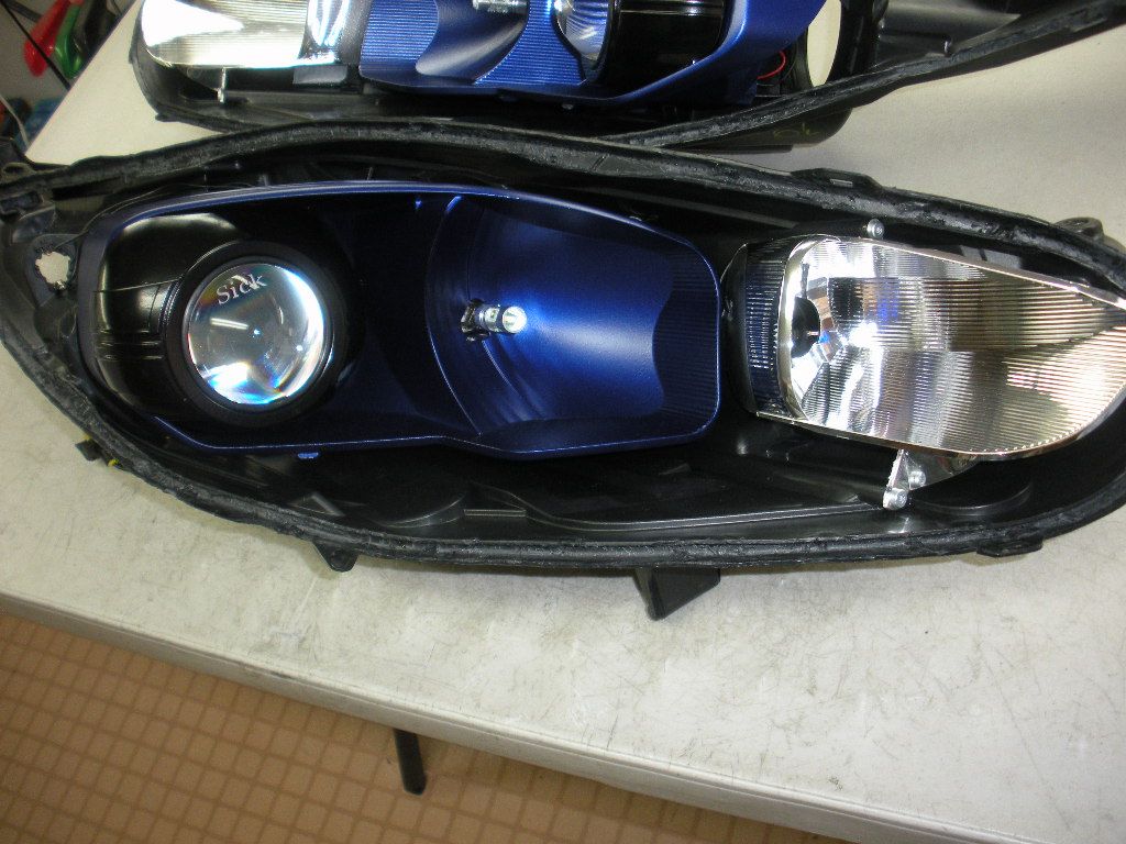
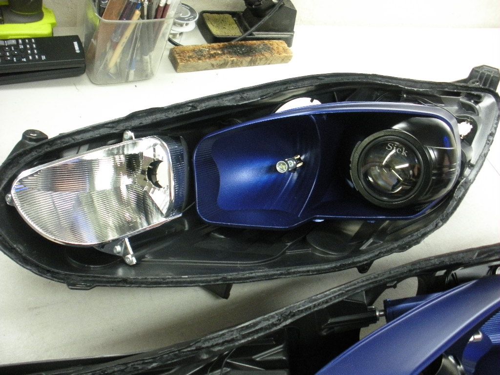
My HID retrofit is almost done. Here are some pictures Brian sent me:
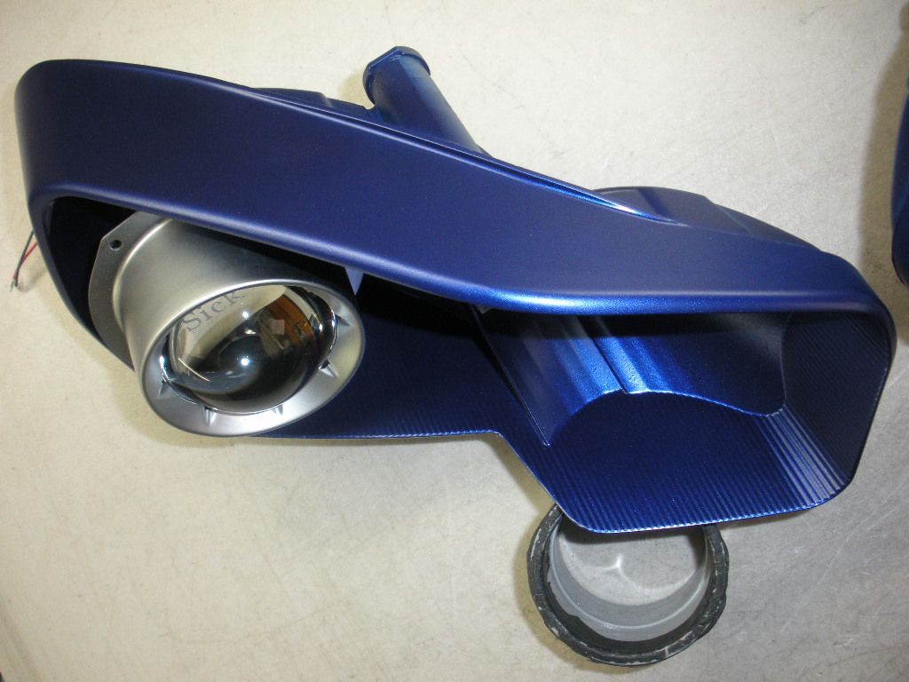
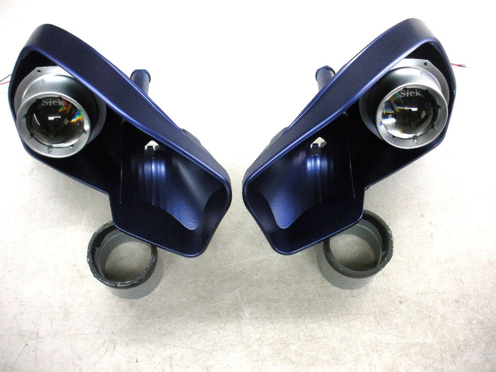
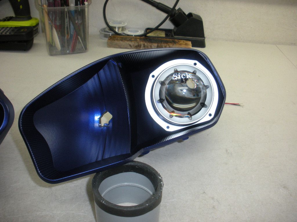
I wanted the reflectors to be painted performance blue, to match the car. This was not as easy to do as I hoped, and all of the chrome needed to be blasted off before the ceramic primer would stick. Now that the color has been sprayed on the reflectors, we are goint to paint the projector shroud covers with ceramic black paint. I'll post pics and a video as soon as the HIDs are completed. Sick HIDs made me a plug and play kit for my mustang, and the wiring harness was very well done. I expect the same quality on my FiST headlight retrofit also. They take a long time tp finish their projects, but their work is well done.


I wanted the reflectors to be painted performance blue, to match the car. This was not as easy to do as I hoped, and all of the chrome needed to be blasted off before the ceramic primer would stick. Now that the color has been sprayed on the reflectors, we are goint to paint the projector shroud covers with ceramic black paint. I'll post pics and a video as soon as the HIDs are completed. Sick HIDs made me a plug and play kit for my mustang, and the wiring harness was very well done. I expect the same quality on my FiST headlight retrofit also. They take a long time tp finish their projects, but their work is well done.
[MENTION=411]westcoaST[/MENTION] any updates on these headlights? Did you get them installed?
My HID retrofit is almost done. Here are some pictures Brian sent me:


I wanted the reflectors to be painted performance blue, to match the car. This was not as easy to do as I hoped, and all of the chrome needed to be blasted off before the ceramic primer would stick. Now that the color has been sprayed on the reflectors, we are goint to paint the projector shroud covers with ceramic black paint. I'll post pics and a video as soon as the HIDs are completed. Sick HIDs made me a plug and play kit for my mustang, and the wiring harness was very well done. I expect the same quality on my FiST headlight retrofit also. They take a long time tp finish their projects, but their work is well done.


I wanted the reflectors to be painted performance blue, to match the car. This was not as easy to do as I hoped, and all of the chrome needed to be blasted off before the ceramic primer would stick. Now that the color has been sprayed on the reflectors, we are goint to paint the projector shroud covers with ceramic black paint. I'll post pics and a video as soon as the HIDs are completed. Sick HIDs made me a plug and play kit for my mustang, and the wiring harness was very well done. I expect the same quality on my FiST headlight retrofit also. They take a long time tp finish their projects, but their work is well done.
Thread Starter
#68
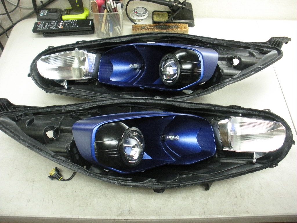
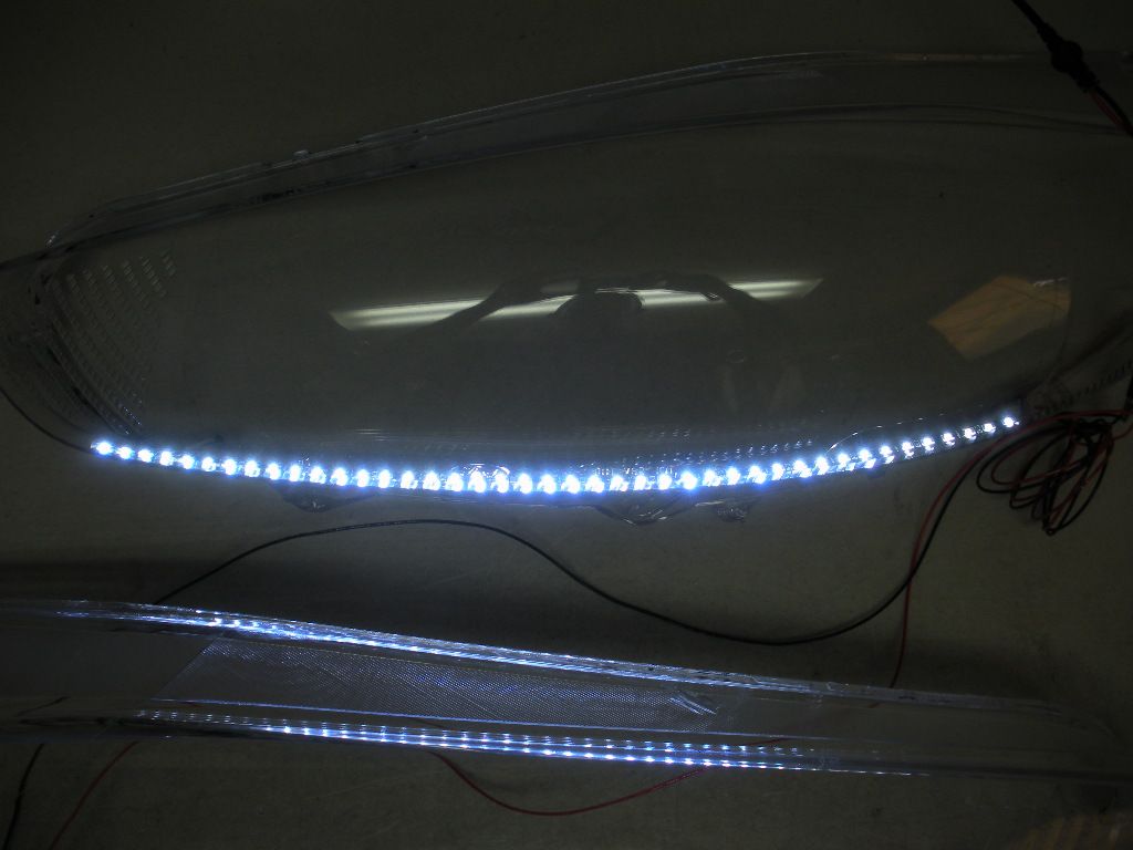
Latest update on the headlights. We are close to shipping, now that the LED strip light has been finalized. I did not like the large LED strip light with lots of gap between the lights. There have been some failures of these lights after a few years. We decided to go with the smaller, more closely spaced LED lights. Brian still has to set up the wire harness, seal the lights and ship them.
I also installed the 6 pt and 2 pt braces from Jim Pierce. I still have to install the Wilwood brakes, the RZL flex fuel system, and the Boomba short shift lever, bushings and Redline leather shift boot.
I also installed the 6 pt and 2 pt braces from Jim Pierce. I still have to install the Wilwood brakes, the RZL flex fuel system, and the Boomba short shift lever, bushings and Redline leather shift boot.


Thread Starter
#71
I'm confused why you killed your high beams? Now you're stuck with half the light you could have.
Any idea which projector, bulb, and ballast you're getting?
Any idea which projector, bulb, and ballast you're getting?
Morimotos specially designed for SICK HIDS, along with his own brand of ballasts and bulbs. Evertthing is guaranteed for life, unlike the places with ballasts that buzz, burn out, etc, after a few hundred cycles.
Hey, I was checking out the part numbers for the Fumoto oil drain valve and noticed a discrepancy.
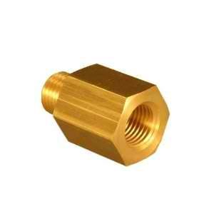
You've got the valve listed as F-107N for the Mishimoto catch can and state it's the same as the oil plug. Fumoto lists the oil drain valve as F-106N.
What's the difference? Did you use the 106N for the oil drain plug? Thanks for the confirmation!
You've got the valve listed as F-107N for the Mishimoto catch can and state it's the same as the oil plug. Fumoto lists the oil drain valve as F-106N.
What's the difference? Did you use the 106N for the oil drain plug? Thanks for the confirmation!
Thread Starter
#76
F106N works on the OCC. I corrected my build. Make sure you cut some notches into the threadded part of the valve to halp drain out all of the oil from the bottom of the OCC. I threw in some stainless steel pot scrubbers to help increase the surface area for the oil mist to turn into oil.
F106N works on the OCC. I corrected my build. Make sure you cut some notches into the threadded part of the valve to halp drain out all of the oil from the bottom of the OCC. I threw in some stainless steel pot scrubbers to help increase the surface area for the oil mist to turn into oil.
Thread Starter
#78
Thread Starter
#79
I wasn't able to install my HID headlights last weekend, but I did get some work done.
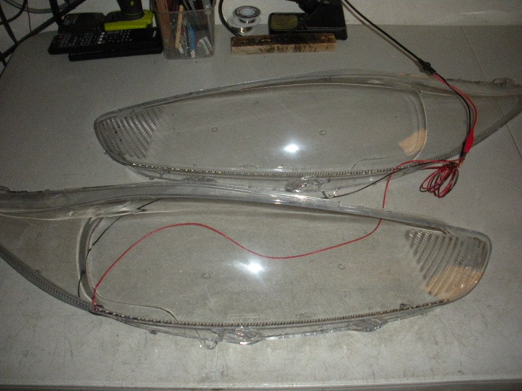
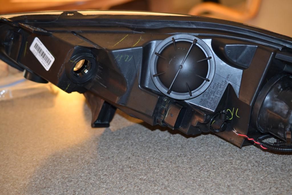
I had LED strips installed along the lower edge of the headlights as part of the retrofit, but these strips were not wired into the plug. After checking with SICKHIDS, I figured I would get some quick release, waterproof electrical connectors. This way, when I have to remove my headlights, for whatever reason, all I need to do is unplug all of the connectors. I got the quick release connectors from Amazon. A pack of five, 2 pin connectors is $12.00 plus change. Here is what the headlights look like with the bare black and red wires for the LED strip.
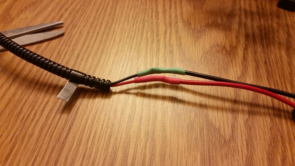
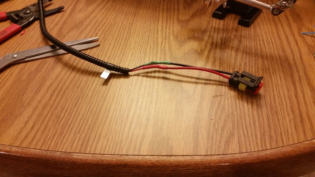
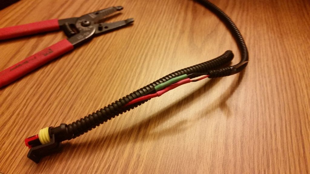
I soldered the wires up to the two pin connector, covered them with shrink tubing, and encased them in split wire cable, so they would look like SICKHIDs work.
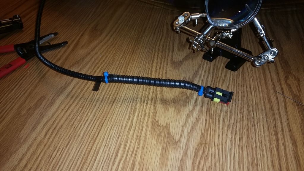
Next, I have to expose the wires for the running lights on the OEM male plug, then solder and cover the mating connectors with the same split wire cover
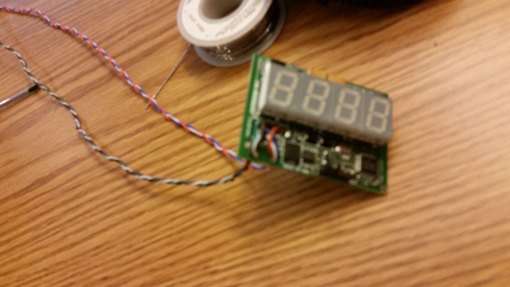
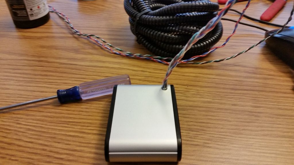
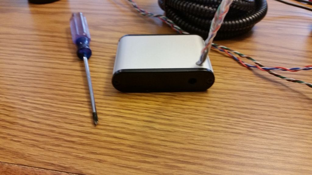
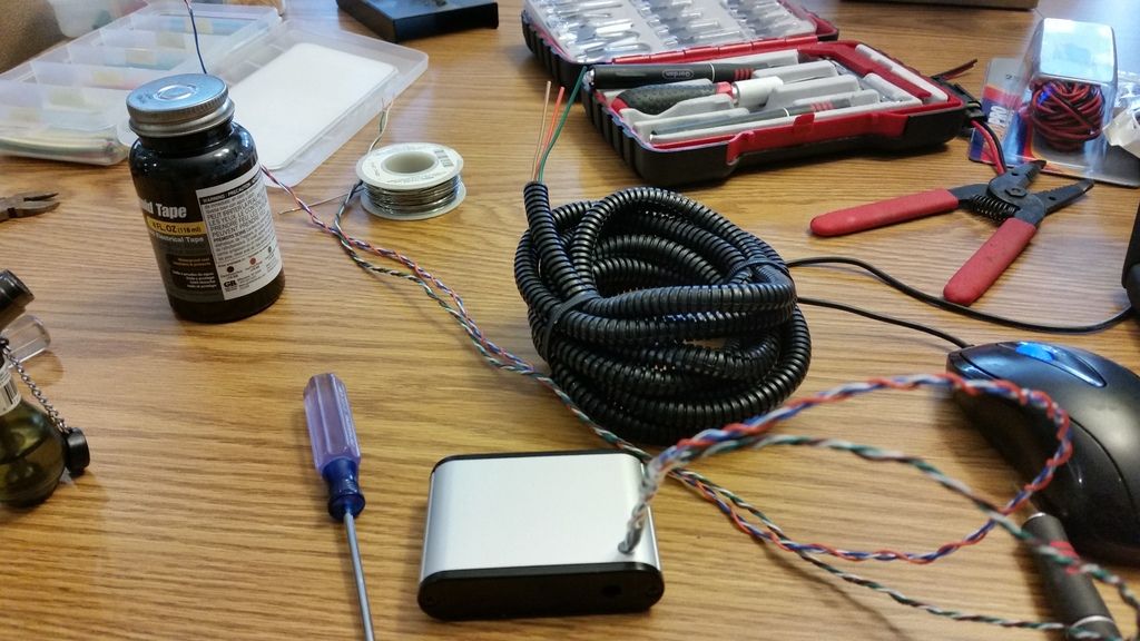
Since I had my soldering equipment out, I decided to modify the Zeitronix Flex Fuel gauge. The wires come out the bottom of the unit, which makes it difficult to mount the gauge using velcro, in the glove box, like I had intended. I wanted to be able to view the gauge with the glove box open, and then close it without the gauge moving around in the glove box. I drilled a hole in the back of the gauge, and stripped the cover, then ran the wires back through the drilled hole. I placed a piece of clear shrink tubing over the wires, and into the drilled hole to serve as a grommet, then further reinforced the end with liquid tape. I covered the wire with split wire cover, and will install the quick disconnect connector tonight.
This weekend I plan on installing the head lights and flex fuel system. I'm also getting Randy at Mountune to create an e40 tune for me.
I had LED strips installed along the lower edge of the headlights as part of the retrofit, but these strips were not wired into the plug. After checking with SICKHIDS, I figured I would get some quick release, waterproof electrical connectors. This way, when I have to remove my headlights, for whatever reason, all I need to do is unplug all of the connectors. I got the quick release connectors from Amazon. A pack of five, 2 pin connectors is $12.00 plus change. Here is what the headlights look like with the bare black and red wires for the LED strip.

I soldered the wires up to the two pin connector, covered them with shrink tubing, and encased them in split wire cable, so they would look like SICKHIDs work.


Next, I have to expose the wires for the running lights on the OEM male plug, then solder and cover the mating connectors with the same split wire cover
Since I had my soldering equipment out, I decided to modify the Zeitronix Flex Fuel gauge. The wires come out the bottom of the unit, which makes it difficult to mount the gauge using velcro, in the glove box, like I had intended. I wanted to be able to view the gauge with the glove box open, and then close it without the gauge moving around in the glove box. I drilled a hole in the back of the gauge, and stripped the cover, then ran the wires back through the drilled hole. I placed a piece of clear shrink tubing over the wires, and into the drilled hole to serve as a grommet, then further reinforced the end with liquid tape. I covered the wire with split wire cover, and will install the quick disconnect connector tonight.


This weekend I plan on installing the head lights and flex fuel system. I'm also getting Randy at Mountune to create an e40 tune for me.
Thread Starter
#80
Install complete
Here are some pictures of my install.
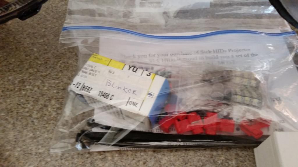
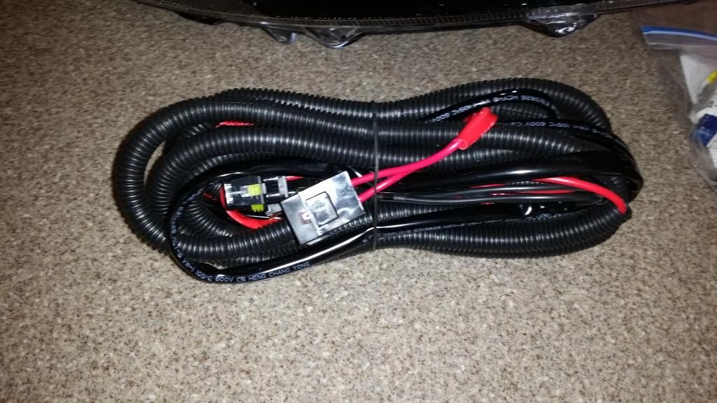
The HID kit comes with a wiring loom, switchback turn signal LEDs, two ballasts, and the retrofitted HID headlights. These headlights have an LED strip along the bottom of the headlight. This requires wiring them into the OEM connector. This is what the passenger side connector looks line. You want to tap into the parking or running lights.
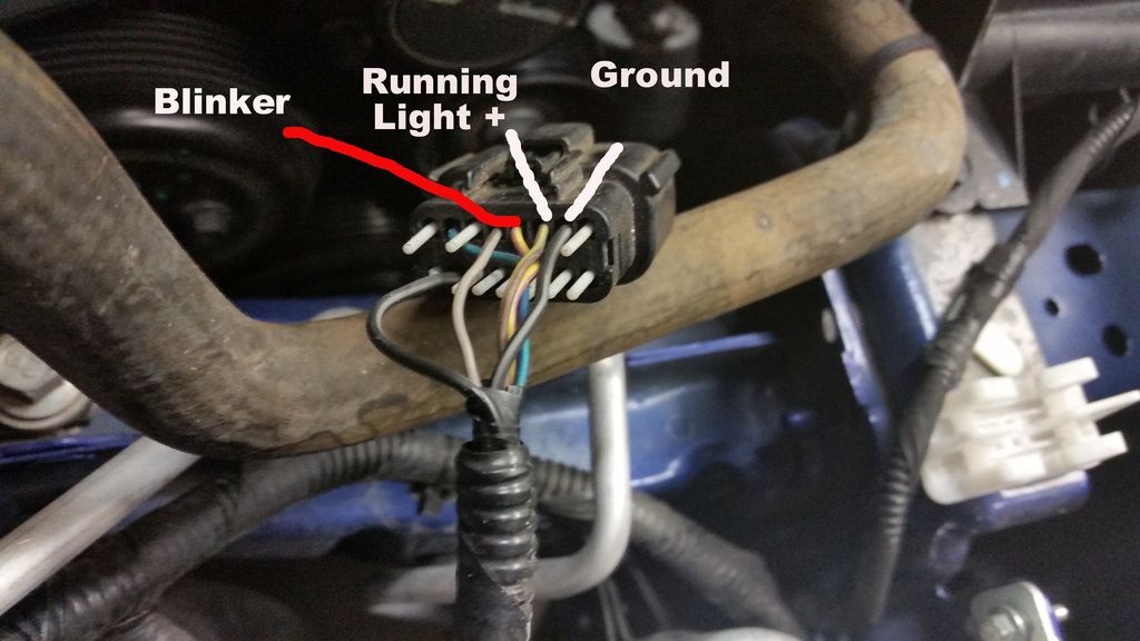
This photo shows which wires you need to tap into. It is the same two wires on the drivers side. Note, the colors are not the same on each side. The wire to the left of the parking/running lights is the flasher wire. If you install switchbacks and you want to slow down the flashing speed, you wire one end of the resistor, or a length of wire that, in turn gets wired to the resistor, the other end of the resistor gets mounted to a metal surface, and the other wire gets grounded to that surface. Make sure you solder all connections because the resistor will get very hot.
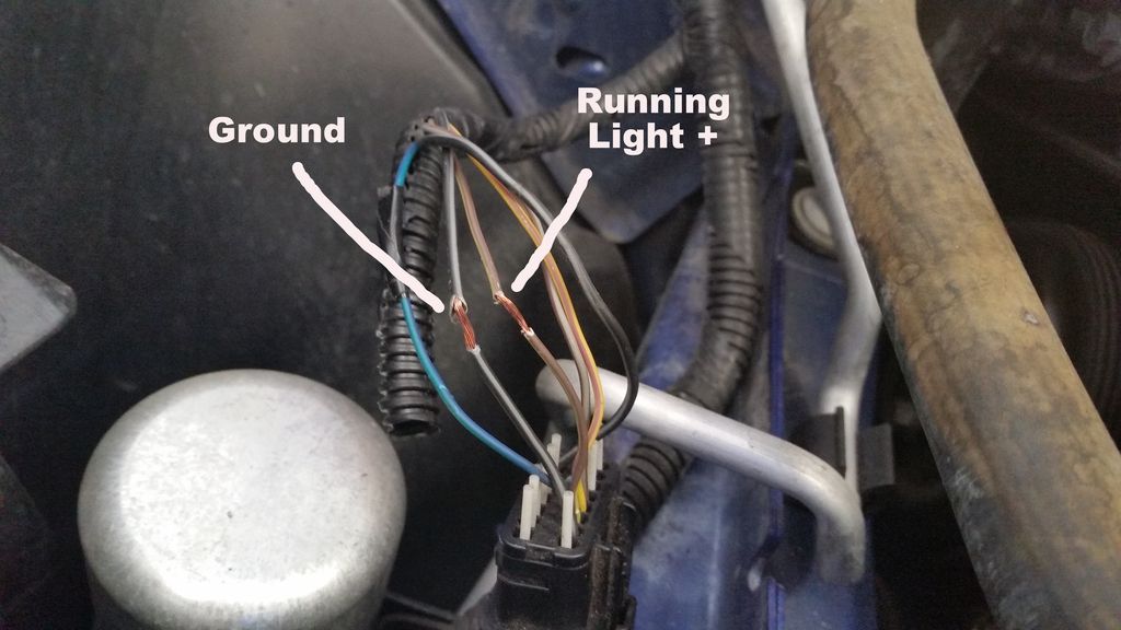
These are the wires to tap into.
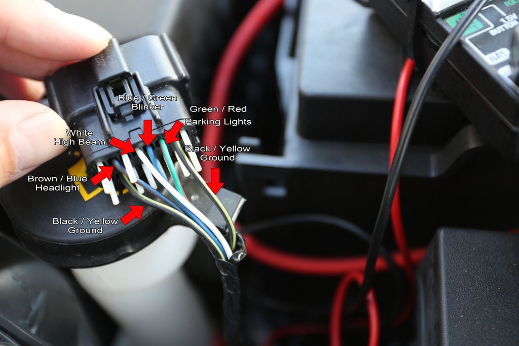
This is the drivers side. The wires on the top row, third from the right end is the parking light, and second from the right is the ground. I used an exacto blade to peel the insulation away.
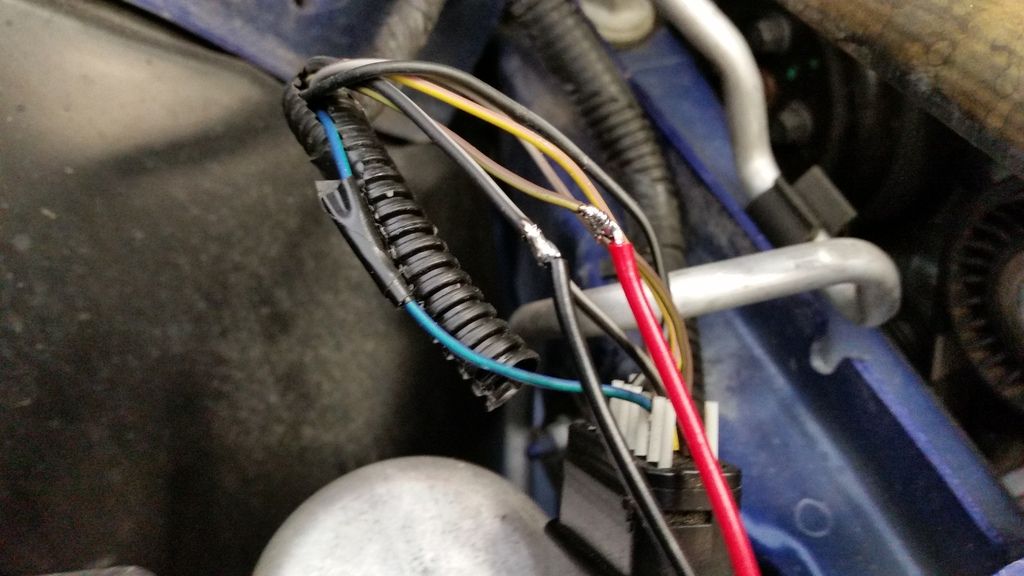
Passengers side
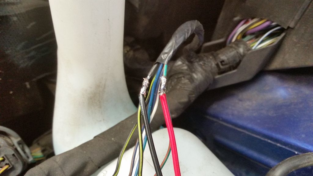
Drivers side.
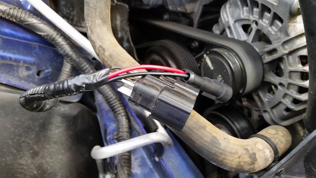
I purchased a two pin waterproof quick connection, and soldered it onto each plug. I used electrical tape to cover each solder joint. Then split corrigated wire cover to make it look OEM. This is the passengers side.
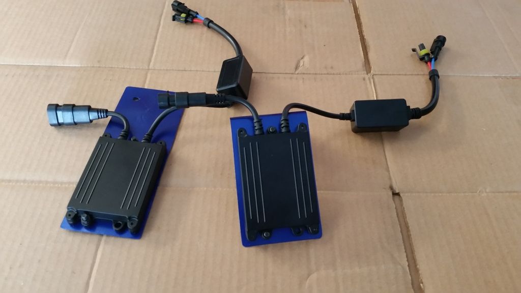
I wanted to mount the ballasts as near as possible to the lights since the 5000K connectors from the headlights are pretty short. I made up some aluminum panels, drilled out two holes to mount the ballast, and drilled the holes in the passenger side, on the frame.
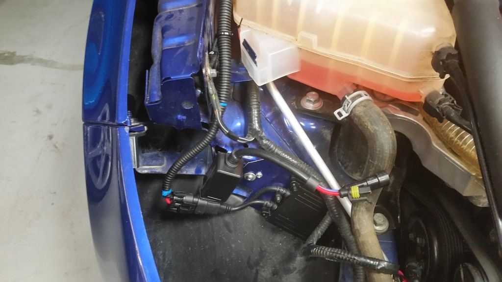
I had originally thought the balast would fit on the crash par part of the frame, so I bent the passengers side plate, but that put the plugs too far from the headlights, so I unbent the plate, and mounted it as shown. This is the passenger's side. I used industrial strength velcro to mount the hardware coming out of the ballast to the plug.
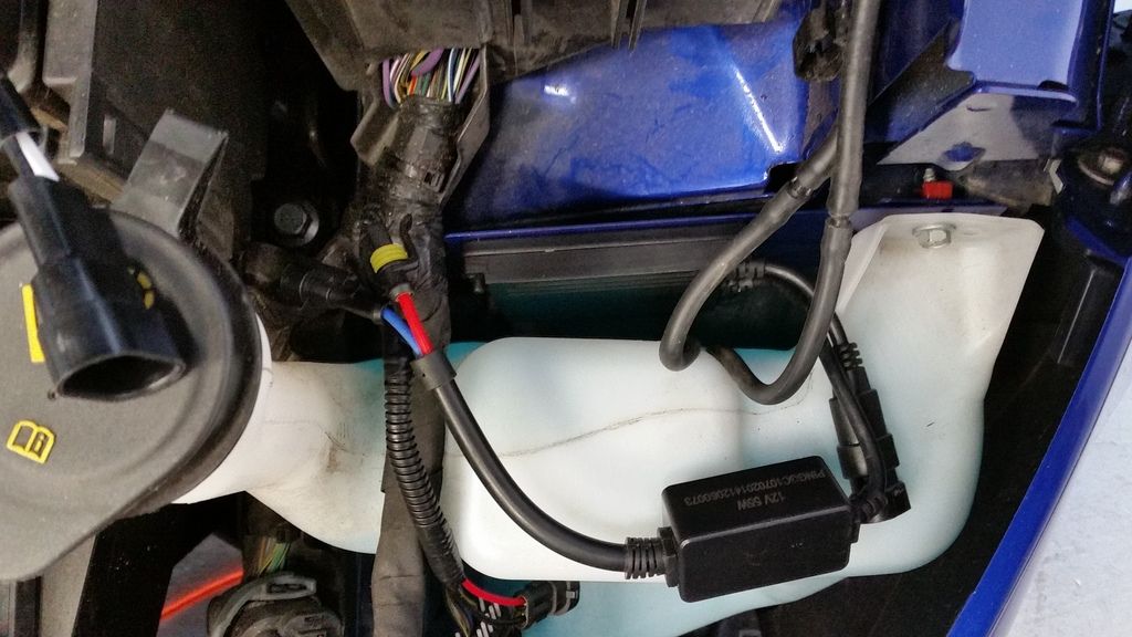
On the drivers side, I mounted the ballast between the body and the washer fluid bottle. I used the fasterner that holds the washer bottle and drilled a hole, and secured the ballast with that fastener.
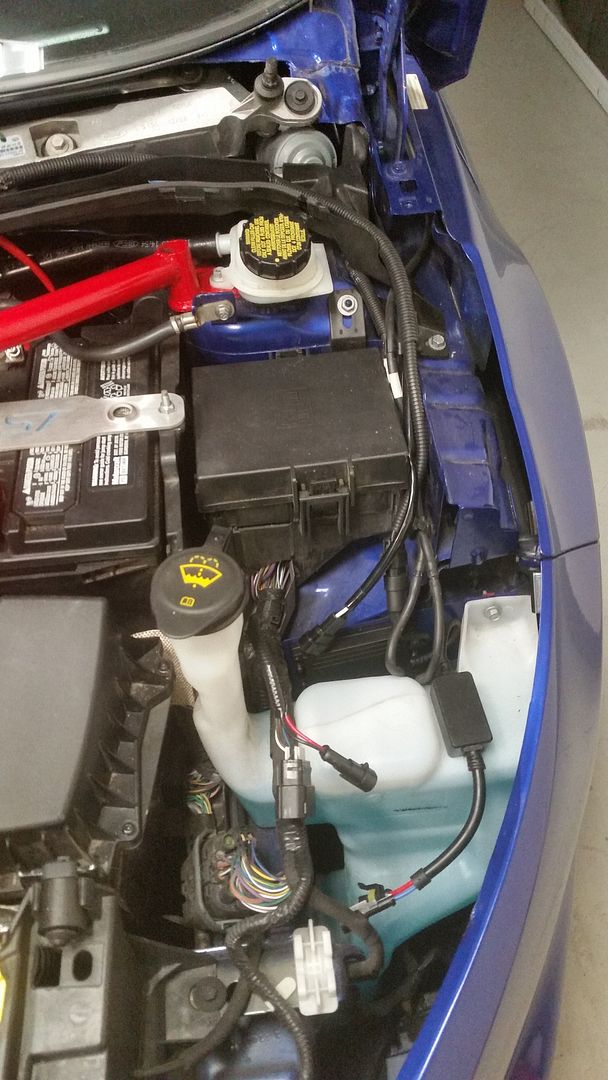
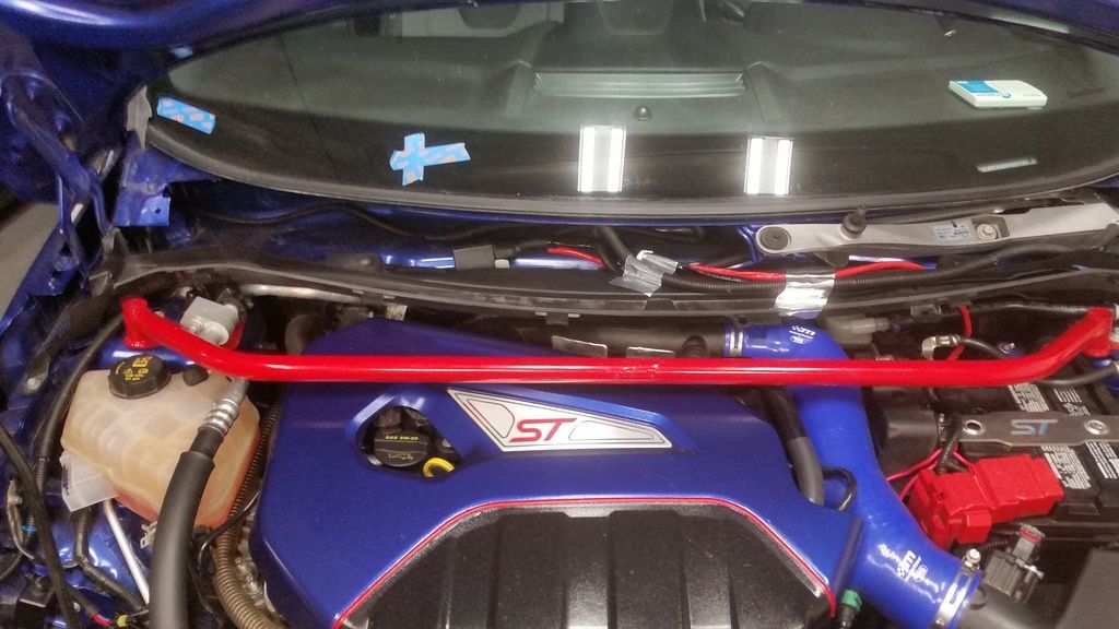
I put all of the wiring between the upper and lower rear cowl. Then I cut into the lower cowl to allow the wiring to pass through to the battery, the passengers side, and the drivers side.
I had pulled the negative battery terminal before I started, so I wouldn't create any problems with fuses or wires. I wrapped the terminal in a shop rag to prevent it from touching anything. I wired the positive terminal to the battery, snaking it around the battery, and attaching it to the positive terminal. I needed to trim the positive terminal cover, to allow the cover to fit with the extra wire. I attached the ground to the ground on the passengers side, then I attached the rest of the plugs (Ballast plug on both sides, trigger on the drivers side, 2 pin plug for the LED strip light), and the OEM plug to the headlights. I started the car up, turned on the lights and everything fired right up. Everything except the switchback LEDs and one parking light. I had to pull the switchbacks and reverse them, and replace the small bulb at the top of the passengers side, headlamp. I installed the headlights, the upper cowl, the wiperblades, and took the rest of these photos.
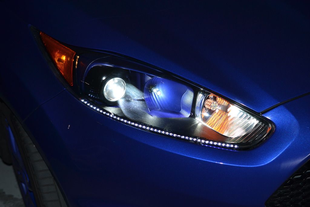
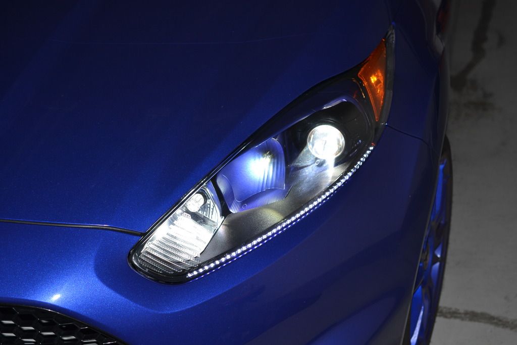
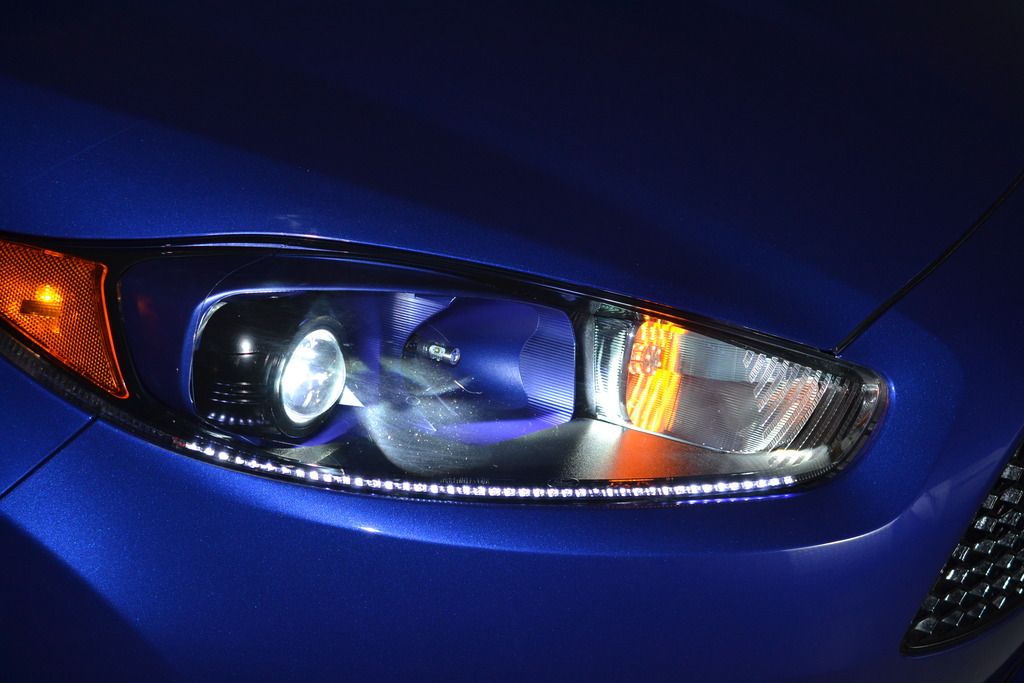
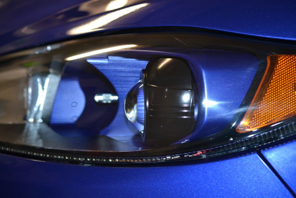
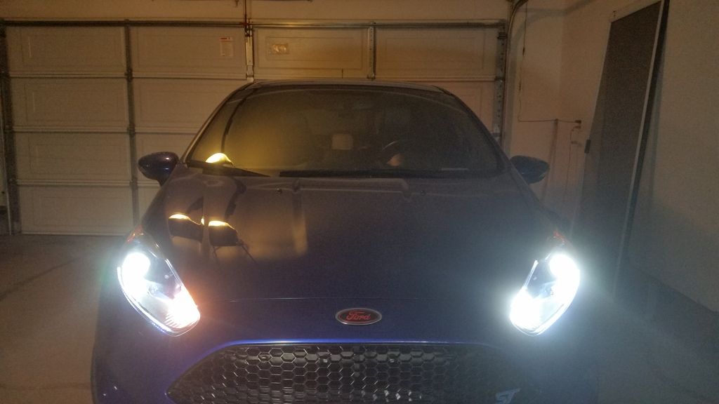
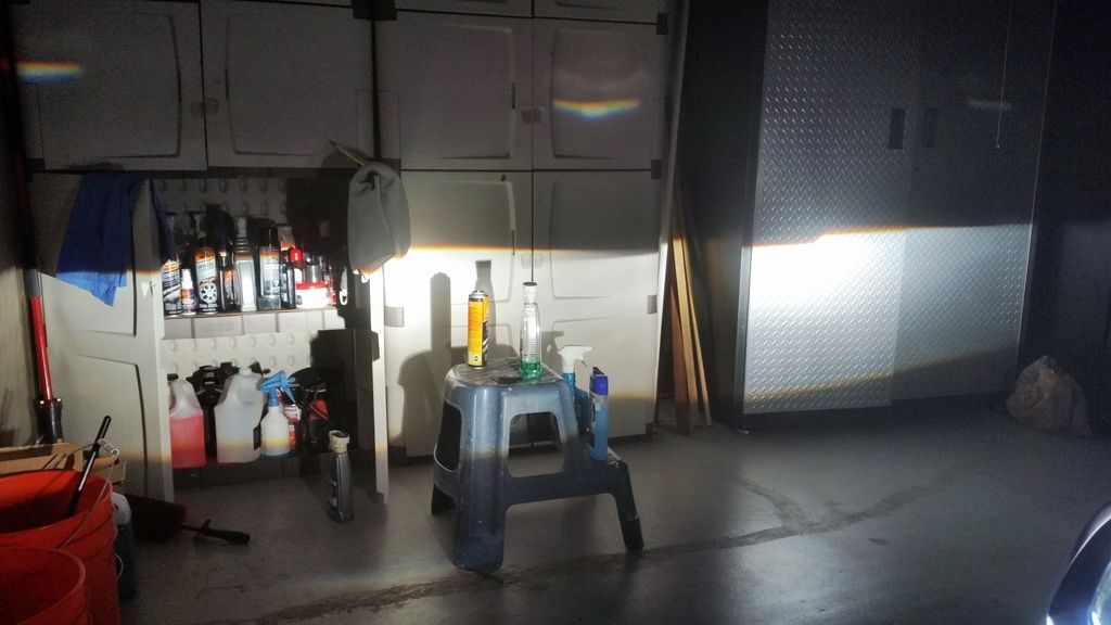
Most of the time it took to install these lights was consumed making decisions how the ballasts were going to be attached, how the wire was going to be routed, and then actually doing it. In the end, the headlights came out looking great, and the wiring routing looks OEM, which what I was going for.
Here are some pictures of my install.
The HID kit comes with a wiring loom, switchback turn signal LEDs, two ballasts, and the retrofitted HID headlights. These headlights have an LED strip along the bottom of the headlight. This requires wiring them into the OEM connector. This is what the passenger side connector looks line. You want to tap into the parking or running lights.

This photo shows which wires you need to tap into. It is the same two wires on the drivers side. Note, the colors are not the same on each side. The wire to the left of the parking/running lights is the flasher wire. If you install switchbacks and you want to slow down the flashing speed, you wire one end of the resistor, or a length of wire that, in turn gets wired to the resistor, the other end of the resistor gets mounted to a metal surface, and the other wire gets grounded to that surface. Make sure you solder all connections because the resistor will get very hot.

These are the wires to tap into.

This is the drivers side. The wires on the top row, third from the right end is the parking light, and second from the right is the ground. I used an exacto blade to peel the insulation away.

Passengers side

Drivers side.

I purchased a two pin waterproof quick connection, and soldered it onto each plug. I used electrical tape to cover each solder joint. Then split corrigated wire cover to make it look OEM. This is the passengers side.

I wanted to mount the ballasts as near as possible to the lights since the 5000K connectors from the headlights are pretty short. I made up some aluminum panels, drilled out two holes to mount the ballast, and drilled the holes in the passenger side, on the frame.

I had originally thought the balast would fit on the crash par part of the frame, so I bent the passengers side plate, but that put the plugs too far from the headlights, so I unbent the plate, and mounted it as shown. This is the passenger's side. I used industrial strength velcro to mount the hardware coming out of the ballast to the plug.

On the drivers side, I mounted the ballast between the body and the washer fluid bottle. I used the fasterner that holds the washer bottle and drilled a hole, and secured the ballast with that fastener.


I put all of the wiring between the upper and lower rear cowl. Then I cut into the lower cowl to allow the wiring to pass through to the battery, the passengers side, and the drivers side.
I had pulled the negative battery terminal before I started, so I wouldn't create any problems with fuses or wires. I wrapped the terminal in a shop rag to prevent it from touching anything. I wired the positive terminal to the battery, snaking it around the battery, and attaching it to the positive terminal. I needed to trim the positive terminal cover, to allow the cover to fit with the extra wire. I attached the ground to the ground on the passengers side, then I attached the rest of the plugs (Ballast plug on both sides, trigger on the drivers side, 2 pin plug for the LED strip light), and the OEM plug to the headlights. I started the car up, turned on the lights and everything fired right up. Everything except the switchback LEDs and one parking light. I had to pull the switchbacks and reverse them, and replace the small bulb at the top of the passengers side, headlamp. I installed the headlights, the upper cowl, the wiperblades, and took the rest of these photos.


Most of the time it took to install these lights was consumed making decisions how the ballasts were going to be attached, how the wire was going to be routed, and then actually doing it. In the end, the headlights came out looking great, and the wiring routing looks OEM, which what I was going for.
Similar threads
-
-
Used performance parts- Both Tips Performance in Rock Hill South Carolina
- Started by Stevesims
- Replies: 7
-
MK8 Ford Fiesta ST performance service manual & maintenance intervals
- Started by fiestanewbie
- Replies: 4
-
How can I setup the ST performance display
- Started by ScaR
- Replies: 1
-
INTRODUCING - The Game Changer in Performance Braking!
- Started by MFactory
- Replies: 11
-
-
Wagner intercooler and TB performance crashbar
- Started by Ganjie
- Replies: 0
-
-
-
Ford Community Posts
-
-
Clutch pedal sticking to the floor
- Latest: TyphoonFiST
-
-
-

