• Sign Up! To view all forums and unlock additional cool features

    Welcome to the #1 Fiesta ST Forum and Fiesta ST community dedicated to Fiesta ST owners and enthusiasts. Register for an account, it's free and it's easy, so don't hesitate to join the Fiesta ST Forum today!


IC Test, Pressure Drop.

Sekred

1000 Post Club
Messages
1,395
Likes
403
Location
Mid North Coast
#1
Be meaning to do this for a while so finally got round to testing my J-Line IC pressure drop across the core.
I am using a Dywer's Magnehelic differential gauge. This gauge has two pressure inputs on the back. One port for measuring above atmospheric pressure and the other port for measuring below atmospheric pressure, vacuum in other words.
With one port connected it measures the input pressure verse the open port-atmospheric.
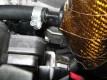
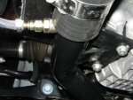
Connect both ports across the core, hot charge pipe and cold charge pipe, it will measure the pressure difference.
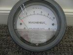
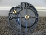
Mag Gauge.jpg

Mag Gauge.2.jpg

Cold pipe fitting.jpg

Hot pipe fitting.jpg

I then took the vehicle out on the road and did a few red line pulls. Hint, play the YouTube clip in the highest HD and in Theatre mode and you can just get a idea of whats happening with the gauge readings.
I also did a 3rd gear and 4th gear roll-on showing the response of the EFR 6258 turbo.
The maximum pressure drop was very close to 2psi.
3rd gear response, 20psi by 3500 rpm.
4th gear response, 20psi by 3165 rpm

[video]https://youtu.be/vry4_-4Eg50[/video]

I would appreciate if someone can load the clip because for some reason I can not do this anymore on my PC.

[video=youtube;vry4_-4Eg50]https://www.youtube.com/watch?v=vry4_-4Eg50[/video]


OP
Sekred

Sekred

1000 Post Club
Messages
1,395
Likes
403
Location
Mid North Coast
Thread Starter #5
What does the beeping indicate?
That's to keep me awake lol, no just joking. My boost gauge has a over boost feature where a alarm beeps. Default is 20psi which I haven't bother to reset and the E-boost controller has a similar feature which is set at 22psi.


Siestarider

Senior Member
Messages
988
Likes
295
Location
Stuart
#6
Awesome data. Considering you are pumping over 30 lbs/min air, less than 2 psi pressure drop across IC seems pretty reasonable to me.

Please correct me if I am reading pics wrongly, but you appear to be measuring upstream and downstream of two 90 degree elbows, some fittings, etc. plus intercooler.


OP
Sekred

Sekred

1000 Post Club
Messages
1,395
Likes
403
Location
Mid North Coast
Thread Starter #7
Awesome data. Considering you are pumping over 30 lbs/min air, less than 2 psi pressure drop across IC seems pretty reasonable to me.

Please correct me if I am reading pics wrongly, but you appear to be measuring upstream and downstream of two 90 degree elbows, some fittings, etc. plus intercooler.
Yes that pretty much correct. On the hot side pipe, just before the elbow and on the cold side pipe, just after the temp/pressure sensor on the plastic fitting.
The pressure drop I would rate as fair. I would have like to have seen 1psi or less. It is a large intercooler and Mishimoto claims its good for up to 500hp, what ever that means. To me it means it should be good enough to flow up to 50 lbs/min, so my reasoning is at a little over 30 lbs/min, I would have expected less than a 2 psi pressure drop. Trouble is, it just my theory and because there is basically very little data on IC pressure drop I can't really compare it to any thing. Guess I just hard to please.


Siestarider

Senior Member
Messages
988
Likes
295
Location
Stuart
#8
Having never looked for pressure drop data on IC's I have nothing to go by. But seems to me pressure loss would be correlated with both higher pressure in and mass air flow in. Be interesting to compare graphs showing air flow vs pressure drop with inlet pressure vs pressure drop.

But the main thing is still delta T for charge air, your data show J-line does a good job managing temps. If we had inlet temp we could calculate all this stuff from your data with basic thermodynamics and see how much of measured pressure drop is required for air temp drop.


Siestarider

Senior Member
Messages
988
Likes
295
Location
Stuart
#9
Not trying to be obtuse. Shorthand for ideal gas law. PV=nRT. n is moles of gas, R is a constant. Assuming constant mass air flow, n and R are both constant.

No power terms in equation. The IC reduces T, therefore PV term is also reduced proportionately. The Temp part is somewhat dependent on internal flow restriction, more turbulence = better delta T across IC. So total pressure drop is a function of both intercooler restriction inducing turbulence, and temperature drop.

Mass air flow (n) is going up with rpm, R is constant, so P has to drop if V is staying constant or increasing. So if you know T in and T out, IC efficiency might be estimated by comparing it to ideal (based solely on temp drop) vs actual (temp drop plus internal friction loss).

Having never thought of this particular application before, I am happy to be corrected if I have it wrong.

If I am right, IC designers might omit the delta T pressure loss part because its required for intercooler to function, and focus on pressure drop due to internal turbulence.

A side thought is that I have read may posts opining IC's can be too big. The only way I can understand this view is if IC is so large it enables some laminar flow, possibly decreasing delta T per surface area. But if both turbulence and delta T are reduced across IC, delta P should also be minimized across IC.

All that theoretical BS aside, there are probably some practical rules of thumb relating delta T and P that would put us in the right ballpark if we knew them.


Messages
435
Likes
108
Location
Campbell
#10
Ideal gas law is applicable if there is no air flow.

Since there is flow, the ∆P should be near zero in an ideal intercooler because the pressure wave between the inlet and outlet should move at the speed of sound and the air in the pipe is flowing a lot slower than mach 1.


Siestarider

Senior Member
Messages
988
Likes
295
Location
Stuart
#11
Ideal gas law is applicable if there is no air flow.

Since there is flow, the ∆P should be near zero in an ideal intercooler because the pressure wave between the inlet and outlet should move at the speed of sound and the air in the pipe is flowing a lot slower than mach 1.
It has been a while, but my recollection is ideal gas law applies to all closed systems. I would say the pipes and IC between turbo compressor and intake valves is a closed system. So there has to be a thermodynamic loss of P if T is reduced in the system.


PhoenixM3

Senior Member
Messages
806
Likes
510
Location
Colorado Springs
#12
My guess is that DHM's race intercooler MAY have a greater pressure loss because of size and the efficiency at which it reduces charge air temp. It doesn't matter for the most part, because there is likely some tradeoff's to achieve the desired effect. Larger ICs will likely (one of you jump in if this doesn't pass the 'sniff test') have a greater loss in boost pressure, because size and outlet temperatures are a part of the equation. I love my race IC, but am only mildly curious to see what, if any pressure loss can be measured.


Messages
435
Likes
108
Location
Campbell
#13
It has been a while, but my recollection is ideal gas law applies to all closed systems. I would say the pipes and IC between turbo compressor and intake valves is a closed system. So there has to be a thermodynamic loss of P if T is reduced in the system.
It's not a closed system. A closed system is like a jar, no flow.

You also have to be a little careful with the ideal gas law because air isn't quite ideal. Moisture in air can go through phase changes depending on P and T and the ideal gas law doesn't do phase change.


Messages
435
Likes
108
Location
Campbell
#14
With a very good intercooler you aren't going to see ∆P across the core due to ∆T, you will just notice that your boost level drops a little or for the same boost your mass flow reading will be higher. Both of those are good outcomes.

Any ∆P you see across the core is just air restriction.


twolf

Active member
Messages
607
Likes
266
Location
Canton
#15
Isn't cooler air more dense? Meaning for a lower "pressure" there are actually more air molecules? I'm not good with science sheeeet at all, I'm a CS major and I haven't taken a science class since HS... lol.

I assume this is basically what you're saying in your post, Wimp Lo.


Messages
435
Likes
108
Location
Campbell
#16
If your turbo is pumping out as much air as possible and the engine is running at a constant RPM, increasing intercooler efficiency will reduce the air temperature, make the air more dense and read less boost pressure.

The wastegate will also see less boost so if your turbo is not maxed out, it will pump more air to maintain the boost level.

Everything effects everything else so it's hard to isolate the effects of one component change.


Siestarider

Senior Member
Messages
988
Likes
295
Location
Stuart
#17
Basic thought experiment: Capture the intercooler at one high pressure instant of time by capping each end off simultaneously faster than a speeding bullet.

We can surely agree it has an inlet presssure, a volume of air, and an outlet pressure. It was working fine before we capped it off, so inlet pressure is greater than outlet pressure, otherwise it could not have worked at all.

Assume air is close enough to ideal gas to ignore correction factors for practical purposes, because it is.

We can identify temperature in front of IC, and behind it, and in front is lower than rear. Because it was working fine before we capped it off, and this is how it exchanges heat from inside to outside.

Now its a closed system and we calculate PV=nRT across tiny vertical slices of IC from inlet to outlet. We now have all the data needed to determine how much actual instantaneous pressure drop between inlet and outlet is created by actual instantaneous heat loss in front and behind IC. Lets just call it kinetic energy for short, since that is what heated (pressurized) air is about.

Using kinetic energy to replace heat simplifies the thought experiment, because we can lump in internal friction through IC with heat loss across core. The volume of our IC cannot change, hence ALL of the pressure loss is due to kinetic energy lost in the trip the charge air takes across the IC between each of our infinitesimal vertical slices.

To make the experiment real, all we need is calculus and real data points.

While the IC must obey the laws of physics, actual performance in real testing (I found some data) suggests maximum possible efficiency is around 95% at 10 psi boost, and it falls off as boost goes up. Minimum pressure drop is about 0.5" across IC for 10 psi boost and it goes up with more boost.

Based on the stuff I found, I believe less than 2 psi pressure drop at the maximum boost (26 psi? I have already forgotten) and delta T Sekred reported is very respectable. OEM IC under those same conditions should indicate 3.5" pressure drop and half the delta T.

For those who like data, CPE has some BMW IC testing on the web. I do not care for their terminology, but data seem useful. Audi forum, HotRod, several others I found somewhat useful.


Messages
435
Likes
108
Location
Campbell
#18
Simplify it even more, imagine a simple horizontal tube the same length as our intercooler.

With no flow and one end cooled a lot, what is the pressure differential between the hot side and the cold side?

It's zero because the pressure wave moves at the speed of sound.

The efficiency number of an intercooler does not relate to air flow, it relates to how efficiently it transfers heat from the intake air to the cooling air blowing through the core.

There are intercoolers with fantastic efficiency that create a lot of pressure drop across the core and there are horribly inefficient intercoolers that create almost zero pressure drop across the core.

We want a combination of high efficiency and low pressure drop (across the core). They are not mutually exclusive but you can wind up with a very large core if you need both.


Top