
-
Sign Up! To view all forums and unlock additional cool features
Welcome to the #1 Fiesta ST Forum and Fiesta ST community dedicated to Fiesta ST owners and enthusiasts. Register for an account, it's free and it's easy, so don't hesitate to join the Fiesta ST Forum today!
Fresh Air for the Fiesta! ST Performance Intake R&D!
- Thread starter mishimoto1
- Start date
Thread Starter
#25
My question now is are you worried about heatsoke? I have read that people with the InGen intake have seen that and with this sample intake being made out of medal wouldn't the same thing happen? I could be wrong just had to ask. Thanks
I do NOT believe anyone who says their metal intake tube doesn't soak. My cp-e pipe got so effing hot it was ridiculous. Covered in gold foil now and it's barely warm to the touch and temps stay 5?-10? above ambient and this is with NO heat shield on my downpipe.
I have an injen intake and i do get heatsoak. But its Arizona, it would be less with perhaps a COBB intake but marginal most likely.
Yes I used to monitor intake temps. When sitting in traffic they get high.
Charge temps I do monitor and I'll post a pic later they stay pretty close to ambient
Charge temps I do monitor and I'll post a pic later they stay pretty close to ambient
Even plastic will heat soak at idle, but while moving my Cobb does a very good job at keeping things just a hair above ambient.
-John
Thread Starter
#26
Project update! Check it out below.
Fresh Air for the Fiesta! ST Performance Intake R&D, Part 3: Making a Silicone Inlet Hose
This is a pretty cool post, something a bit out of the ordinary for our projects. We typically utilize our existing silicone boots in our intercooler kits, intake systems, etc. For this project, we decided to manufacture the first portion of our intake system from a wire-reinforced silicone hose. This would facilitate an easier installation, and it would also provide a smooth airflow transition from the small turbocharger compressor inlet to our intake?s large pipe diameter. Since we like to show you what goes into developing our prototypes, check out the process for creating our silicone turbo inlet hose below!
Printing Our Fixture
The hose we have in mind will follow the path of the stock induction hose, which is actually a plastic piece on the stock ST. Before beginning our silicone project, we needed a fixture that would serve as a base for the silicone layers that will be applied. After making a model in Solidworks, we fired up the 3D printer and watched as it churned out our component.

Printing 3D silicone Ford Fiesta ST intake hose fixture

Printing 3D silicone Fiesta ST intake hose fixture
And our end result is below!

3D-printed silicone Fiesta ST intake hose fixture
As you can see, the diameter of this pipe gradually increases from small to large. The outer diameter of this fixture will become the inner diameter of our completed silicone inlet hose.
Silicone Inlet Hose Creation
We?ve got some work to do! Our first layer of material is standard silicone, which is wrapped around the fixture until the entire piece is covered in a single, flat layer.

Silicone hose layer 1 for Fiesta ST parts

Silicone hose layer 1 for Ford Fiesta ST intake hose
After some careful work, our first layer was complete.

Silicone hose layer 1 for Ford Fiesta ST intake hose
Our second layer would be a slightly different material. Check it out below.

Fiber-embedded silicone layer for Fiesta ST parts
This layer is composed of fiber-embedded silicone, and it is the key component for the rigidity and strength needed in our end product. The fibers provide greater pressure tolerance, making it ideal for any pressurized system (e.g., cooling, CAC).
Like the standard silicone, this layer is wrapped around the fixture in a similar fashion.

Fiber-reinforced silicone layer for Fiesta ST parts
The next portion of this build is a bit out of the ordinary for your typical silicone hose. Normal hoses and boots encompass the silicone and fiber layers, but for this inlet hose, we will be using metal wire to further reinforce the integrity of the hose. Why? Well, standard silicone hoses tend to collapse under extreme vacuum or suction, which is exactly what this hose will see. All our hoses that attach directly to a turbocharger compressor inlet are wire-reinforced for additional strength.
The wire is wound around the hose throughout its entire length.

Wire-reinforced layer for Fiesta ST parts
The image below shows our Fiesta prototype next to a cutaway of our Subaru WRX turbo inlet hose, which also features wire reinforcement. Our final rendition of the Fiesta induction hose will likely feature thicker wire with less winds, similar to the WRX piece.

Wire-reinforced layer (top) and Subaru WRX inlet hose (bottom)
Our next layer is yet another slice of silicone on the sandwich that is our Fiesta inlet hose. Or perhaps it?s more like a wrap? Anyway, another layer of silicone is applied over the wire.

Third layer of silicone material for Ford Fiesta ST intake
Another layer of fiber-reinforced material is added, followed by a final layer of plain silicone, resulting in our four-ply induction hose. I won?t bore you with more images of Mike wrapping these last two layers on the fixture, but I assure you he did it!
We?re not finished yet. There are a few more steps as we progress toward a completed silicone hose. Our next step is to wrap the hose in a protective tape to keep the silicone in place for baking. This tape is resistant to our baking temperature and will keep the silicone in position during the process.

Baking tape being applied to Fiesta ST intake hose
This ?tape? is not sticky and does not adhere to the silicone. It is wound tightly around the pipe to compress the silicone to its final shape.

Silicone Fiesta ST intake hose ready for baking
The tedious portion of the process is now complete. From here out, it is as simple as baking a batch of brownies. We fired up the oven, popped in our hose, and waited while the silicone cured.
Note: Don?t do this at home. Baking silicone in the oven releases a pungent odor that will fill your house and ruin any meals cooked in that oven for the next few days.

Silicone hose baking for Fiesta ST parts
Once we completed the numerous baking sessions and the hose had cooled, we trimmed the edges to our desired length. This revealed the numerous layers of material, similar to what you would see with any of our silicone products.

Ford Fiesta ST intake silicone hose
The baking tape was then removed, revealing our final product!

Mishimoto silicone turbo intake hose, final product
We even test fit this piece on the car with our intake piping!

Silicone Ford Fiesta ST intake hose installed
Coming Up!
Before dyno testing we still have one important portion of our intake to tackle: the airbox. We have some pretty interesting plans for the design, so expect a post crammed with cutting, bending, welding, and plenty of flying sparks.
Thanks for reading!
-John
Fresh Air for the Fiesta! ST Performance Intake R&D, Part 3: Making a Silicone Inlet Hose
This is a pretty cool post, something a bit out of the ordinary for our projects. We typically utilize our existing silicone boots in our intercooler kits, intake systems, etc. For this project, we decided to manufacture the first portion of our intake system from a wire-reinforced silicone hose. This would facilitate an easier installation, and it would also provide a smooth airflow transition from the small turbocharger compressor inlet to our intake?s large pipe diameter. Since we like to show you what goes into developing our prototypes, check out the process for creating our silicone turbo inlet hose below!
Printing Our Fixture
The hose we have in mind will follow the path of the stock induction hose, which is actually a plastic piece on the stock ST. Before beginning our silicone project, we needed a fixture that would serve as a base for the silicone layers that will be applied. After making a model in Solidworks, we fired up the 3D printer and watched as it churned out our component.
Printing 3D silicone Ford Fiesta ST intake hose fixture
Printing 3D silicone Fiesta ST intake hose fixture
And our end result is below!
3D-printed silicone Fiesta ST intake hose fixture
As you can see, the diameter of this pipe gradually increases from small to large. The outer diameter of this fixture will become the inner diameter of our completed silicone inlet hose.
Silicone Inlet Hose Creation
We?ve got some work to do! Our first layer of material is standard silicone, which is wrapped around the fixture until the entire piece is covered in a single, flat layer.
Silicone hose layer 1 for Fiesta ST parts
Silicone hose layer 1 for Ford Fiesta ST intake hose
After some careful work, our first layer was complete.
Silicone hose layer 1 for Ford Fiesta ST intake hose
Our second layer would be a slightly different material. Check it out below.
Fiber-embedded silicone layer for Fiesta ST parts
This layer is composed of fiber-embedded silicone, and it is the key component for the rigidity and strength needed in our end product. The fibers provide greater pressure tolerance, making it ideal for any pressurized system (e.g., cooling, CAC).
Like the standard silicone, this layer is wrapped around the fixture in a similar fashion.
Fiber-reinforced silicone layer for Fiesta ST parts
The next portion of this build is a bit out of the ordinary for your typical silicone hose. Normal hoses and boots encompass the silicone and fiber layers, but for this inlet hose, we will be using metal wire to further reinforce the integrity of the hose. Why? Well, standard silicone hoses tend to collapse under extreme vacuum or suction, which is exactly what this hose will see. All our hoses that attach directly to a turbocharger compressor inlet are wire-reinforced for additional strength.
The wire is wound around the hose throughout its entire length.
Wire-reinforced layer for Fiesta ST parts
The image below shows our Fiesta prototype next to a cutaway of our Subaru WRX turbo inlet hose, which also features wire reinforcement. Our final rendition of the Fiesta induction hose will likely feature thicker wire with less winds, similar to the WRX piece.
Wire-reinforced layer (top) and Subaru WRX inlet hose (bottom)
Our next layer is yet another slice of silicone on the sandwich that is our Fiesta inlet hose. Or perhaps it?s more like a wrap? Anyway, another layer of silicone is applied over the wire.
Third layer of silicone material for Ford Fiesta ST intake
Another layer of fiber-reinforced material is added, followed by a final layer of plain silicone, resulting in our four-ply induction hose. I won?t bore you with more images of Mike wrapping these last two layers on the fixture, but I assure you he did it!
We?re not finished yet. There are a few more steps as we progress toward a completed silicone hose. Our next step is to wrap the hose in a protective tape to keep the silicone in place for baking. This tape is resistant to our baking temperature and will keep the silicone in position during the process.
Baking tape being applied to Fiesta ST intake hose
This ?tape? is not sticky and does not adhere to the silicone. It is wound tightly around the pipe to compress the silicone to its final shape.
Silicone Fiesta ST intake hose ready for baking
The tedious portion of the process is now complete. From here out, it is as simple as baking a batch of brownies. We fired up the oven, popped in our hose, and waited while the silicone cured.
Note: Don?t do this at home. Baking silicone in the oven releases a pungent odor that will fill your house and ruin any meals cooked in that oven for the next few days.
Silicone hose baking for Fiesta ST parts
Once we completed the numerous baking sessions and the hose had cooled, we trimmed the edges to our desired length. This revealed the numerous layers of material, similar to what you would see with any of our silicone products.
Ford Fiesta ST intake silicone hose
The baking tape was then removed, revealing our final product!
Mishimoto silicone turbo intake hose, final product
We even test fit this piece on the car with our intake piping!
Silicone Ford Fiesta ST intake hose installed
Coming Up!
Before dyno testing we still have one important portion of our intake to tackle: the airbox. We have some pretty interesting plans for the design, so expect a post crammed with cutting, bending, welding, and plenty of flying sparks.
Thanks for reading!
-John
It is great seeing the R&D that does into making a product. As an engineer, I see all the work daily that goes into designing and making a product. Most people just think this stuff just magically shows up without any need to design and develop it. There is a lot of work to understand how the factory stuff functions, make everything fit, and make sure the end result provides an improvement and not a detriment. So many aftermarket products are poorly designed and cause more problems than just leaving the factory stuff. I have owned a number of those products over the years.
Keep up the good work!!
Keep up the good work!!
![[popcorn]](/images/smilies/popcorn.gif "Popcorn [popcorn]") Woot!
Woot!
Thread Starter
#31
It is great seeing the R&D that does into making a product. As an engineer, I see all the work daily that goes into designing and making a product. Most people just think this stuff just magically shows up without any need to design and develop it. There is a lot of work to understand how the factory stuff functions, make everything fit, and make sure the end result provides an improvement and not a detriment. So many aftermarket products are poorly designed and cause more problems than just leaving the factory stuff. I have owned a number of those products over the years.
Keep up the good work!!
Keep up the good work!!
Im really liking this thread so far, Mishimoto ![[cheers]](/images/smilies/icon_smile_cheers.gif "Cheers [cheers]")
Out of curiosity, do you take intake noise into account when designing the airbox or is it all about flow?
Thanks again for all of the feedback and response guys!
-John
Thread Starter
#32
Time for another update! Check it out below.
Fresh Air for the Fiesta! ST Performance Intake R&D, Part 4: Airbox Design and Fabrication
We?re getting closer to dyno testing! Our intake piping and turbo inlet hose are now complete. A well-designed airbox is the last portion of our intake design before we begin performance testing. The airbox will provide a shield for the filter to reduce the impact of engine bay heat. It also allows us to create a volume for cold air to enter from the stock duct, routing directly to our filter.
The airbox design was pretty extensive for this project, so this is a long post. Sit back, crack open your favorite beverage, and read on!
Airbox Fabrication
We started this process with cardboard templates. These templates helped us quickly adjust and modify the shape and bends until we had a design that provided for appropriate clearance. The space between the battery and air duct is quite slender, so the design will need to be precise.

Ford Fiesta ST intake airbox cardboard template
Below is a look at what we have to work with regarding the stock duct. As you can see, the duct routes downward before entering the box.

Ford Fiesta ST intake airbox cardboard template
We then fit this portion of our airbox with the air filter in place to check clearances.

Ford Fiesta ST intake airbox cardboard template
Once we confirmed the overall shape and the bends needed, we laid this template out on a steel sheet to create our first portion of the airbox.

Ford Fiesta ST intake airbox cardboard template
Off to the band saw to make our cuts!

Fiesta ST parts fabrication
A few bends of our prototype, and we had the first portion of our box in steel.

Fiesta ST parts fabrication
Check out this piece in place on the vehicle!

Fiesta ST parts fabrication

Fiesta ST parts fabrication
Now we tackle the next portion of the box, the side with pipe entry. This will not only shroud the filter, but it will also provide for support and placement of the pipe.
We designed this portion a bit differently. After dimensions were pulled from the existing three sides, we drew a model of the projected piece in Solidworks and then printed a template. This template was then glued to a steel plate and cut into shape.

Ford Fiesta ST intake airbox fabrication

Ford Fiesta ST intake airbox fabrication
The opposite side was then constructed in a similar manner and tacked into place.

Ford Fiesta ST intake airbox fabrication
One interesting feature not yet discussed is the mounting points for the airbox, specifically those on the base. The stock airbox uses two posts that slide into grommets on the chassis. We wanted to use these mounting points with our design, so we designed an identical post. For accuracy, we designed these components in Solidworks and printed them using our 3D printer. Once complete, the posts were adhered to the base of the box in the proper location. Check it out!

Fiesta ST parts fabrication
The final piece needed was an airbox lid that would fully encompass the filter and isolate it from the warm engine bay. We spent a good amount of time designing this piece, as we wanted it to follow the contour of the body and engine compartment. Check out the beginnings of this piece!

Fiesta ST parts fabrication

Fiesta ST parts fabrication
This will be converted to steel as well!

Fiesta ST parts fabrication
But wait ? there?s more! We wanted to add a bit of uniqueness to the design of our airbox. Our engineers noted an area near the fender well that should be exposed to additional airflow. Taking a cue from our oil cooler bracket design for the Focus ST, we used the hexagonal grille pattern to open up the driver?s side of the airbox.
Check out our 3D-printed prototype piece.

Airbox fabrication
This piece was then installed on the side of the airbox,

Airbox fabrication
? and the airbox was installed on the vehicle.

Airbox fabrication
We still need to evaluate the grid addition to decide if it will be included in the final design. We want to ensure that this component does not have a negative impact on intake temperatures or airflow entering through the front duct.
Final Testing Prototype
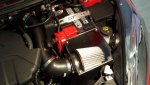
Below is a look at our first prototype fully prepared for dyno testing!

Mishimoto intake prototype

Mishimoto intake prototype

Mishimoto intake prototype

Mishimoto intake prototype
Coming Up!
We are prepared to test both the sound and power produced by our prototype intake! Check back next time for a compilation from our pulls, as well as a summary of our results.
Thanks for reading!
-John
Fresh Air for the Fiesta! ST Performance Intake R&D, Part 4: Airbox Design and Fabrication
We?re getting closer to dyno testing! Our intake piping and turbo inlet hose are now complete. A well-designed airbox is the last portion of our intake design before we begin performance testing. The airbox will provide a shield for the filter to reduce the impact of engine bay heat. It also allows us to create a volume for cold air to enter from the stock duct, routing directly to our filter.
The airbox design was pretty extensive for this project, so this is a long post. Sit back, crack open your favorite beverage, and read on!
Airbox Fabrication
We started this process with cardboard templates. These templates helped us quickly adjust and modify the shape and bends until we had a design that provided for appropriate clearance. The space between the battery and air duct is quite slender, so the design will need to be precise.
Ford Fiesta ST intake airbox cardboard template
Below is a look at what we have to work with regarding the stock duct. As you can see, the duct routes downward before entering the box.
Ford Fiesta ST intake airbox cardboard template
We then fit this portion of our airbox with the air filter in place to check clearances.
Ford Fiesta ST intake airbox cardboard template
Once we confirmed the overall shape and the bends needed, we laid this template out on a steel sheet to create our first portion of the airbox.
Ford Fiesta ST intake airbox cardboard template
Off to the band saw to make our cuts!
Fiesta ST parts fabrication
A few bends of our prototype, and we had the first portion of our box in steel.
Fiesta ST parts fabrication
Check out this piece in place on the vehicle!
Fiesta ST parts fabrication
Fiesta ST parts fabrication
Now we tackle the next portion of the box, the side with pipe entry. This will not only shroud the filter, but it will also provide for support and placement of the pipe.
We designed this portion a bit differently. After dimensions were pulled from the existing three sides, we drew a model of the projected piece in Solidworks and then printed a template. This template was then glued to a steel plate and cut into shape.
Ford Fiesta ST intake airbox fabrication
Ford Fiesta ST intake airbox fabrication
The opposite side was then constructed in a similar manner and tacked into place.
Ford Fiesta ST intake airbox fabrication
One interesting feature not yet discussed is the mounting points for the airbox, specifically those on the base. The stock airbox uses two posts that slide into grommets on the chassis. We wanted to use these mounting points with our design, so we designed an identical post. For accuracy, we designed these components in Solidworks and printed them using our 3D printer. Once complete, the posts were adhered to the base of the box in the proper location. Check it out!
Fiesta ST parts fabrication
The final piece needed was an airbox lid that would fully encompass the filter and isolate it from the warm engine bay. We spent a good amount of time designing this piece, as we wanted it to follow the contour of the body and engine compartment. Check out the beginnings of this piece!
Fiesta ST parts fabrication
Fiesta ST parts fabrication
This will be converted to steel as well!
Fiesta ST parts fabrication
But wait ? there?s more! We wanted to add a bit of uniqueness to the design of our airbox. Our engineers noted an area near the fender well that should be exposed to additional airflow. Taking a cue from our oil cooler bracket design for the Focus ST, we used the hexagonal grille pattern to open up the driver?s side of the airbox.
Check out our 3D-printed prototype piece.
Airbox fabrication
This piece was then installed on the side of the airbox,
Airbox fabrication
? and the airbox was installed on the vehicle.
Airbox fabrication
We still need to evaluate the grid addition to decide if it will be included in the final design. We want to ensure that this component does not have a negative impact on intake temperatures or airflow entering through the front duct.
Final Testing Prototype
Below is a look at our first prototype fully prepared for dyno testing!
Mishimoto intake prototype
Mishimoto intake prototype
Mishimoto intake prototype
Mishimoto intake prototype
Coming Up!
We are prepared to test both the sound and power produced by our prototype intake! Check back next time for a compilation from our pulls, as well as a summary of our results.
Thanks for reading!
-John
John, nice work. It looks like the lid will need to be removed when trying to remove the driver side headlight when removing the front clip? It is neccessary to have the lid extend that far, perhaps keep the width same as stock? It looks like 3 bolts for the lid, but still... Currently there's no need to remove the OE airbox to remove the headlight.
John, nice work. It looks like the lid will need to be removed when trying to remove the driver side headlight when removing the front clip? It is neccessary to have the lid extend that far, perhaps keep the width same as stock? It looks like 3 bolts for the lid, but still... Currently there's no need to remove the OE airbox to remove the headlight.
John, nice work. It looks like the lid will need to be removed when trying to remove the driver side headlight when removing the front clip? It is neccessary to have the lid extend that far, perhaps keep the width same as stock? Currently there's no need to remove the OE airbox to remove the headlight.
It looks like they're trying to shield that grille piece from the rest of the engine bay. I'd be willing to bet that the top of the airbox would come off fairly easily, which would give you access to the headlight. One extra step, but not terrible, IMO.
Something like this where the lid is easily removed for cleaning without having to remove the headlamp...
I don't think you need to remove the headlamp to clean the filter for this. Koozy's concern was the accessibility of the headlamp itself.
Similar threads
-

-

-
-

-

-
 Fresh cobb stg1 91 octane logs, + e20+ cobb stg1 91 octane logs - help interpreting
- Started by Clint Beastwood
- Replies: 2
-

-

-
-