• Sign Up! To view all forums and unlock additional cool features

    Welcome to the #1 Fiesta ST Forum and Fiesta ST community dedicated to Fiesta ST owners and enthusiasts. Register for an account, it's free and it's easy, so don't hesitate to join the Fiesta ST Forum today!


CMB Brake Duct Testing

Siestarider

Senior Member
Messages
988
Likes
295
Location
Stuart
#1
CMbuildz Racing sent me a set of their aluminum brake ducts for test and evaluation. My next track day is 2/14, but I had a chance to install one side yesterday so thought I would post and add to it as information is gained.


Pull wheel, remove two 15 mm bolts from rear of hub, winkle the rotor/caliper assembly off hub. Note bungee cord holding rotor/caliper assembly to front spring above. Probably better ways to do this, but none faster.


Stock dust shield is held on with three 8 mm bolts. Easy.


Aluminum duct replacing stock. Same 3 8 mm bolts. Easy. Mirror image ducts make it impossible to install wrong one.


View from hub rear. 2" duct overlaps about 1/2" of inside rotor air vane opening, probably hard to see in pic but this is the best of my attempts to show.

Various measurements: hub 5" diameter and 3/8" thick. Rotor vane opening 5 3/4" diameter and fully exposed behind hub face (except for all the other parts inboard of rotor opening). CMB vent 2" OD, 1 13/16" ID.

I had all the parts on hand to neck down my 3" fog light facia ducts and install 2" hose to brake duct.


But when I pulled the fender liner aside, I realized my hard duct opening backside was angled wrong to accept connector stack, IC hose in the way, so have to pull front end off and revise rear side of duct to make connection. What I get for installing duct before having a hose size or route worked out.

My plan is to get the passenger side worked out and fully operational for testing on track, compare to stock drivers side using stock pads and rotors.


Chuckable

Active member
Messages
559
Likes
90
Location
South Florida
#4
Looking forward to results, too!

CMBuildz, do you think there is any value in covering the ball joint boot to have a layer of heat protection? I believe the Ford Racing version for the Mustang uses material as a shield between the rotor and ball joint.

Siestarider, how in the world did you cut the fog light trim piece and add the honeycomb?


OP
S

Siestarider

Senior Member
Messages
988
Likes
295
Location
Stuart
Thread Starter #5
Razor knife cuts out the "fake" parts easily. Bug screen attached from rear of fog light facia with pop rivets. Hardest part is getting the tabs around fog light out and back in front clip, they are tight. I posted about doing it somewhere on here maybe last year.

Forgot to add note to install of CMB, I strapped bungee on caliper before I removed it from hub, makes it a lot easier to winkle free of hub with all that weight safely suspended so it will not damage brake lines during or after removal.


Chuckable

Active member
Messages
559
Likes
90
Location
South Florida
#6
Razor knife cuts out the "fake" parts easily. Bug screen attached from rear of fog light facia with pop rivets. Hardest part is getting the tabs around fog light out and back in front clip, they are tight. I posted about doing it somewhere on here maybe last year.

Forgot to add note to install of CMB, I strapped bungee on caliper before I removed it from hub, makes it a lot easier to winkle free of hub with all that weight safely suspended so it will not damage brake lines during or after removal.
Don't remember seeing it but I'll look, thanks.


OP
S

Siestarider

Senior Member
Messages
988
Likes
295
Location
Stuart
Thread Starter #7
Installed drivers side intake and hose this weekend. First observation, a 3" duct behind fake fog light vents will not fit past IC hoses (I am running Cobb's IC at present). Ended up rebuilding a smaller air box with sheet aluminum and enough duct tape to seal 3" external vent to a 2.5" to 2" adapter for hose, built it slightly mashable, was able to get it fit and nose back on car.

Basically, with the whole vent and connection box at facia pushed as far as possible adjacent to and parallel with fog light mount box, and 2.5" coupler, it works. But it would be a lot easier to just loose fog lights and take hose straight from them. Connection to CMB ducts a piece of cake by comparison.

I will post the best pics shortly. Anyone have a favorite method of suspending hose beneath car so it will not get friction burns/holes from running? I mounted it over my undertray but the 90 to get back to rear of brake duct looks a little wimbly to me under lower A arm.


Messages
431
Likes
73
Location
simi valley
#8
Installed drivers side intake and hose this weekend. First observation, a 3" duct behind fake fog light vents will not fit past IC hoses (I am running Cobb's IC at present). Ended up rebuilding a smaller air box with sheet aluminum and enough duct tape to seal 3" external vent to a 2.5" to 2" adapter for hose, built it slightly mashable, was able to get it fit and nose back on car.

Basically, with the whole vent and connection box at facia pushed as far as possible adjacent to and parallel with fog light mount box, and 2.5" coupler, it works. But it would be a lot easier to just loose fog lights and take hose straight from them. Connection to CMB ducts a piece of cake by comparison.

I will post the best pics shortly. Anyone have a favorite method of suspending hose beneath car so it will not get friction burns/holes from running? I mounted it over my undertray but the 90 to get back to rear of brake duct looks a little wimbly to me under lower A arm.
This is how I suspended mine [MENTION=1391]Siestarider[/MENTION]
Just drilled to small holes vertical from each other to the splash shield/fender liner. Then used a decent zip tie to hold it snug not to tight... Have to allow some free movement
ImageUploadedByTapatalk1454394545.091549.jpg


OP
S

Siestarider

Senior Member
Messages
988
Likes
295
Location
Stuart
Thread Starter #9
Ah, I mounted my brake cooling hose under the lower A arm because i worried about the gap between driveshaft and lower A arm being potentially abusive. My undertray takes care of the place you tied yours off, supports hose nicely. Its that 90 to rear of rotor I am worried about.


OP
S

Siestarider

Senior Member
Messages
988
Likes
295
Location
Stuart
Thread Starter #11


Inside nose fog vent flange re-oriented parallel with fog light enclosure


New aluminum airbox under flange with 3" x 2" adaptor.


3" box and fitting interfered with IC. Cut box to smallest possible, still would not fit. Went to 2.5" x 2" adapter and built smaller box. Managed to get it all in place. with most of the original 3" fog vent duct still feeding 2.5" adapter.

For this approach, just go with 2" fog vent, or easier still, loose fog light and adapt to rear of fog light box. I spent way too much time trying to get the larger vent openings to work. I am running Cobb IC, in case your IC is different, clearance to side of the IC inlet hose is the issue.


The easy part. This pic loaded upside down.


I ran hose under the lower A arm, but I have undertray still on, new version, to support most of it. Running it between lower A and driveshaft and hanging it per CMB advice may be better option. Also loaded upside down, have to learn how to fix that with edit function.

Next is plenty of temp paint on both sides before track day. I also want to log both front wheels to see if TVC is a major factor tracking with LSD, if so, it could affect brake cooliing.


Chuckable

Active member
Messages
559
Likes
90
Location
South Florida
#12
A plug and play solution would be so much easier, but thanks to Siestarider and others who are paving the way for these track mods.


OP
S

Siestarider

Senior Member
Messages
988
Likes
295
Location
Stuart
Thread Starter #13

Re-routed hose to CMB recommended, between lower A arm and driveshaft. Removed 11" of hose run, good deal.

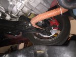
Hose run to front fog facia vent


Brake temp paint and caliper temp strips applied to CMB duct side.


Drivers side stock set up for track tomorrow.

Results tomorrow night, GLW and the creek don't rise.


OP
S

Siestarider

Senior Member
Messages
988
Likes
295
Location
Stuart
Thread Starter #17


Ducted side, inner rotor outside edge ran cooler than outer rotor outside edge, may be as much as 500 degrees difference, but the paint wore badly enough hard to say for certain.
Outside rotor at hub exceeded 750 F but not 1000 F. Caliper temp strips maybe reached 250 F on top, did not register heat on lower strip.


Stock side, rotor edge pic did not come out but no paint showed anywhere on either inner or outer rotor edge.

Outsde rotor at hub showed no difference between cooled and not cooled.

Caliper temp strips both showed clear 250 F temps on stock side.

This is sum of three sessions today at PBIR, 70 F average ambient, stock pads, last day on these BFG SC2 tires. Tires are shot, still have braking but not enough lateral grip to match personal best time. No lack of trying and no mercy for brakes. Undertray failed at end of first session, the other two sessions were run with 2" air dam extension only.

I could not feel anything on pedal but braking when I wanted it. No deficiencies. Tracking records show brakes performed at least as well as prior best on linear deceleration. Maybe a little better, loss of lateral g's due to wear did not seem to affect linear g's.

My take is that CMB Racing ducts showed a measurable difference with these somewhat primitive testing methods, provide better brake cooling than stock.

If I were developing them, I would try opening a flap from the hub side of the 2" round air duct to enable more air to enter rotor hub, the ducted side definitely ran a cooler inner rotor, seems to me getting more air into the hub would equalize the benefits.


Messages
435
Likes
108
Location
Campbell
#19
If I were making ducts (and I might make a pair for myself), I would angle the duct upward to go with the rotation of the rotor and create a bigger oval opening instead of round.

I would also create a duct with tight gaps to the rotor hat to funnel a lot of air in to the vents because air in the vents cools both sides evenly unlike air blown on only the inside of the rotor.

If I can get the gaps tight enough, I might try to open up the bottom side of the "dust shield" to expose the rotor to more air flow. I might try an air deflector if I do that.

That might be too much work for a retail product and I don't know if it would be more effective until I try but that is the way I would go.


Chuckable

Active member
Messages
559
Likes
90
Location
South Florida
#20
My take is that CMB Racing ducts showed a measurable difference with these somewhat primitive testing methods, provide better brake cooling than stock.

If I were developing them, I would try opening a flap from the hub side of the 2" round air duct to enable more air to enter rotor hub, the ducted side definitely ran a cooler inner rotor, seems to me getting more air into the hub would equalize the benefits.
Thanks for the real world testing. The suggestions seems to validate race car designs which funnel air into the center of the rotor so that it is expelled evenly through the venting in the center. If the inner side of the rotor was cooled several hundred degrees compared to the outer, then there appears to be plenty of airflow to work with. Now it's just a matter of designing a product that can get the air into the center of the rotor. That won't be easy with an axle in the way.


Similar threads


Top